Revision History
| Version | Revision Date | Author | Change Description |
|---|---|---|---|
| v1.2 | 20260904 | Yuna | Dual-Arm Robot User Manual for Main Controller V2.2.11 |
Safety and Responsibility Guidelines
The copyright and ownership of this manual belong to Shenzhen LimX Dynamics Technology Co., Ltd. and its affiliates (collectively referred to as "LimX Dynamics"). Without written authorization from LimX Dynamics, no individual or organization may copy, scan, store, distribute, reprint, sell, transfer, modify, or otherwise use all or part of this manual for themselves or others. This manual and its contents are intended only for operating and using this product and may not be used for any other purpose.
To avoid illegal acts, possible injury, and losses, please strictly observe the following requirements:
- Before using this product, carefully read this document to understand your rights, responsibilities, and safety instructions. Failure to comply may result in property loss or safety hazards. By using this product, you indicate that you fully understand and accept all terms in this document. Operate strictly according to the instructions and take full responsibility for your actions and any related consequences.
- This product is not a toy and is not recommended for persons under 18 years old. Keep children away from the product and exercise special caution when operating it in environments where children are present.
- This product should not be used in crowded areas. During use, ensure that people remain outside a 1 m radius from the robot. LimX Dynamics assumes no responsibility for injury or loss caused to relevant personnel due to improper operation.
- Unauthorized disassembly, modification, or non-standard repair of the product is strictly prohibited. LimX Dynamics is not responsible for equipment faults or damage caused by such actions.
- Do not use this product in extreme environments, such as high temperature, low temperature, or corrosive chemical environments. LimX Dynamics is not responsible for equipment issues caused by such conditions.
- Under normal use conditions, issues caused by natural component wear or battery aging are not considered product quality issues, and LimX Dynamics assumes no responsibility for them.
- This product must not be used for any activity that endangers national security, including but not limited to support for terrorism, nuclear facilities, biochemical weapon development, or the design and use of weapons of mass destruction.
- Please confirm that you are not subject to any trade restrictions or sanctions; otherwise, you may not be able to use LimX Dynamics products and services normally.
- LimX Dynamics is committed to ensuring product compliance worldwide. Please comply with the laws and regulations of your region and pay attention to relevant compliance requirements.
- You must comply with the export-control laws and regulations applicable in your region.
- You must undertake to use this product for legitimate purposes and agree to accept all terms in this document.
- LimX Dynamics reserves the right of final interpretation of this agreement and may update or adjust it as needed.
1 Product Overview
1.1 Introduction
The TRON 2 Dual-Arm Robot is an embodied robotics research platform designed for scientific research. Its dual-arm configuration gives users the flexibility to develop and test new ideas. Open low-level interfaces and support for Python and C++ reduce the barriers to embodied intelligence research.
The product is available in two configurations: a Fixed-stand version for tabletop manipulation tasks and a Mobile Dual-Arms Version that adds a Mobile Base for mobile manipulation tasks.
1.2 Product Specifications
| Parameter Category | Parameter | TRON 2 EDU Version | TRON 2 Standard Version | Notes |
|---|---|---|---|---|
| — indicates not available, o indicates optional, and ✓ indicates standard equipment. | ||||
| Mechanical Parameters | Material | Aluminum alloy, plastic | Aluminum alloy, plastic | |
| Degrees of Freedom | 7 DOF per arm 2 DOF for the head |
7 DOF per arm 2 DOF for the head |
||
| Dimensions | Dual Arms | · Shoulder width: 447 mm · Arm length: 730 mm (excluding grippers) |
· Shoulder width: 447 mm · Arm length: 730 mm (excluding grippers) |
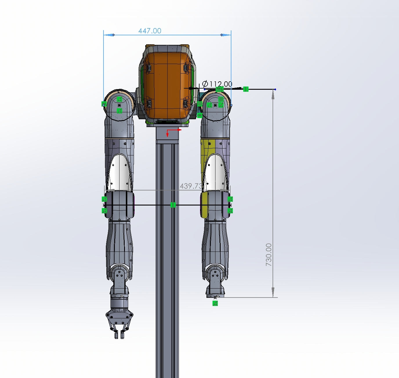 |
| Top Expansion Area | Width: 146 mm; depth: 170 mm | Width: 146 mm; depth: 170 mm | ||
| Functions | Secondary Development | ✔ | — | |
| Dual-Arm Teleoperation Method | VR device (PICO 4 Ultra) | — | ||
| Data Collection and Local Storage | ✔ | — | ||
| Dual-Arm Safety Boundary Protection | ✔ | — | ||
| Dual-Arms Configuration Performance | Maximum End Effector Load | 5 kg per arm with the arm fully extended 3 kg rated |
5 kg per arm with the arm fully extended 3 kg rated |
|
| Maximum End-Effector Speed | 5 m/s | 5 m/s | ||
| Maximum End-Effector Acceleration | 36 m/s² | 36 m/s² | ||
| Repeat Positioning Accuracy | ±0.5 mm | ±0.5 mm | ||
| Teleoperation Delay | 100 ms | 100 ms | ||
| End-Effector Type | Gripper, Dexterous Hand | Gripper, Dexterous Hand | ||
| Gripper Performance | Gripping Force: 20 N Maximum Gripper Stroke: 85 mm |
Gripping Force: 20 N Maximum Gripper Stroke: 85 mm |
||
| Electrical Parameters | Battery Output Voltage | 46.8 V | 46.8 V | |
| Maximum Battery Power | 2800 W | 2800 W | ||
| Support for Battery Replacement | ✔ | ✔ | ||
| Battery Type | Ternary lithium battery | Ternary lithium battery | ||
| Battery Capacity | 9 Ah | 9 Ah | ||
| Charging Power | 542 W | 542 W | ||
| Charging Input Voltage/Current | 100~240 V/8 A | 100~240 V/8 A | ||
| Charging Output Voltage/Current | 54.275 V/10 A | 54.275 V/10 A | ||
| Charging Time | - 20–80%: 30 min; - 20–100%: 54 min |
- 20–80%: 30 min; - 20–100%: 54 min |
||
| Sensor Configuration | Waist RGBD Camera | √ | √ | |
| IMU | √ | √ | ||
| Head RGBD Camera | Standard on the Dual-Arms Configuration | — | ||
| Wrist RGBD Camera | Standard on the Dual-Arms Configuration | — | ||
| Communication Interfaces | Ethernet Port | ✓ (1 port) | ✓ (1 port) | |
| USB 3.0 Port | ✓ (1 port) | ✓ (1 port) | ||
| EtherCAT Port | ✓ (2 ports) | ✓ (2 ports) | ||
| RS485 Port | ✓ (1 port) | ✓ (1 port) | ||
| Peripheral Charging Interfaces | 24 V Power Output Port | ✓ (2 ports) | ✓ (2 ports) | |
| 48 V Power Output Port | ✓ (1 port) | ✓ (1 port) | ||
| Power Supply Interface | External Power Supply Port | ✓ (1 port) | ✓ (1 port) | |
| Developer Expansion Module | Architecture | Intel Core Ultra | — | |
| Storage | 2 TB | — | ||
| Interfaces | 3 × ETH ports; 3 × USB 3.0 ports; 1 × 24 V power input; 1 × 12 V power output |
— | ||
| Software Compatibility and Developer Tools | SDK | √ | — | |
| Robot Management Platform | √ | √ | ||
| Data Platform | ✔ | — | ||
| VR Teleoperation Software | ✔ | — | ||
| Simulation Platform | ✔ | — | ||
| Software Compatibility | Compatible with Python and C++ development environments; compatible with ROS 1/ROS 2 |
— | ||
1.3 Packing List
- Flight Case
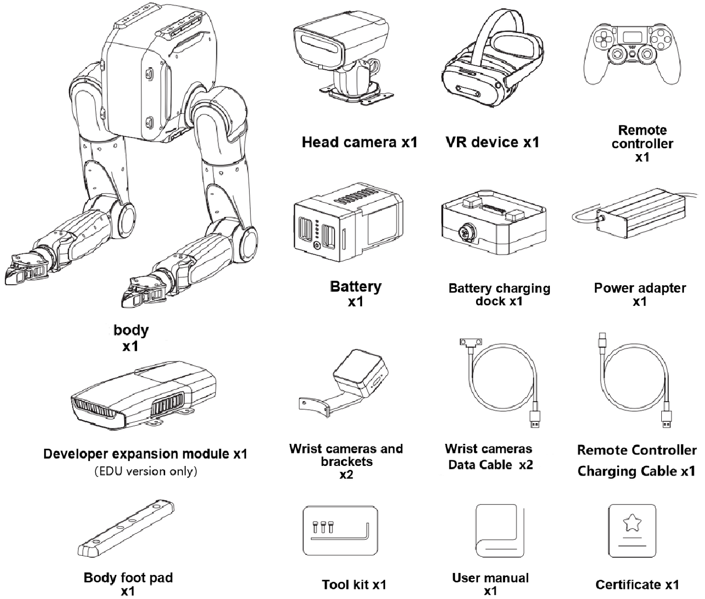
Carton |
Carton |
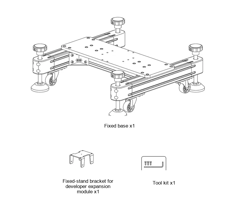 |
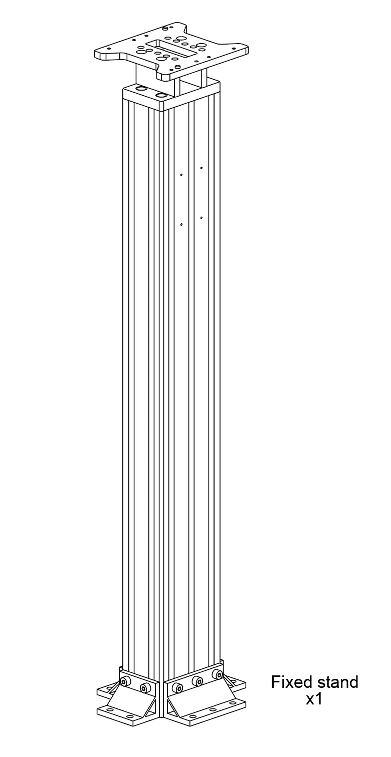 |
Wooden Crate (Mobile Dual-Arms Version upgrade only) |
Carton (Mobile Dual-Arms Version upgrade only) |
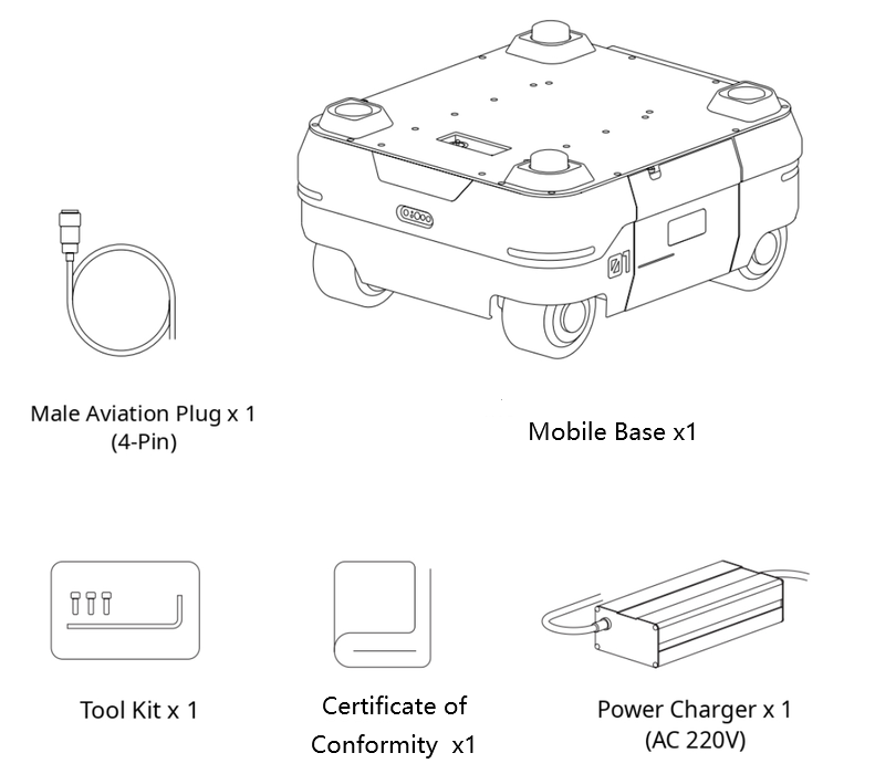 |
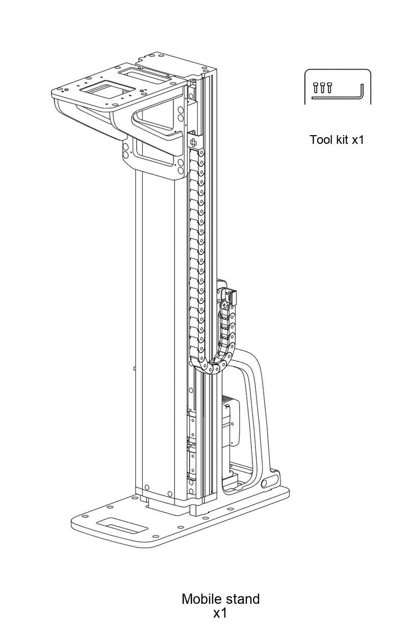 |
1.4 Body Components and Ports
1.4.1 Body Components
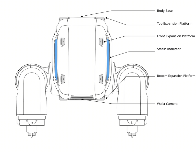
| Component/Port | Function | Component/Port | Function |
|---|---|---|---|
| Status Indicator | Displays robot status, including operating mode, faults, and Low Battery Warnings | Peripheral Expansion Platform | Provides top, front, and bottom mounting areas. All threaded holes are M4 and are used to secure external devices. |
1.4.2 Robot Body Receptacle Ports
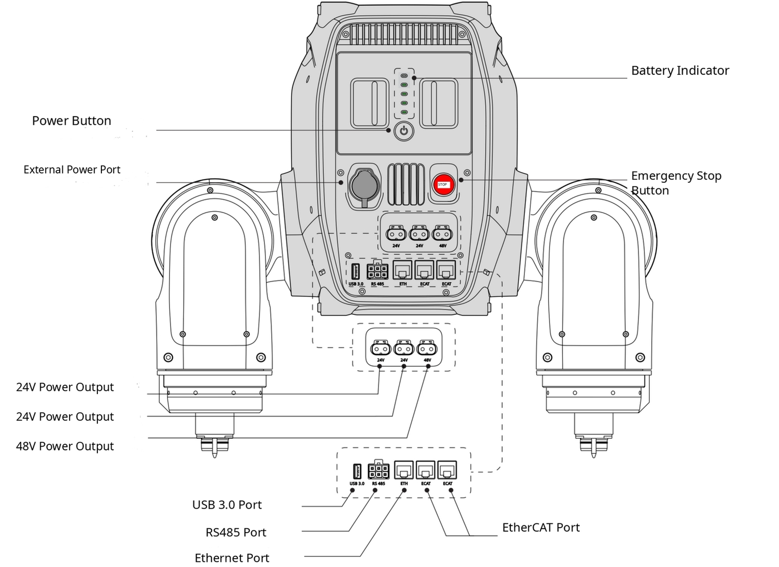
| Component/Port | Function | Component/Port | Function |
|---|---|---|---|
| Power Button | Powers the robot on or off | Battery Level Indicator | Displays the current robot Battery Level |
| External Power Supply Port | Connects the external Power Adapter | Emergency Stop Button | Cuts power to the motors and places the robot in Torque-Off Mode |
| 24 V Power Output Port | LCB female connector; regulated 24 V DC output; rated current 5 A; maximum current 20 A | 48 V Power Output Port | LCB female connector; regulated 48 V DC output; rated current 10 A; maximum current 20 A |
| USB 3.0 Port | USB-A 3.0 port for external devices | Ethernet Port | Gigabit Ethernet port for a computer, router, or other communication module |
| RS485 Port | Connects external devices | EtherCAT Port | Connects external devices |
1.4.3 Developer Expansion Module Ports
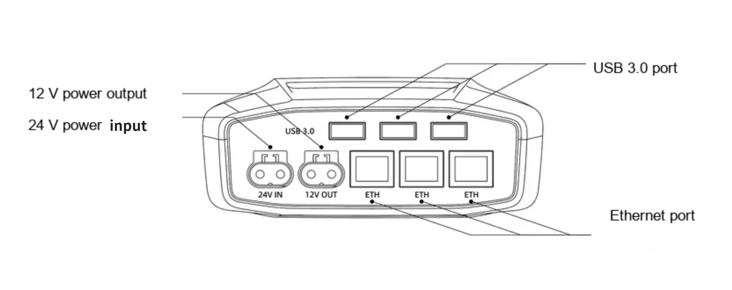
| Component/Port | Function | Component/Port | Function |
|---|---|---|---|
| 12 V Power Output Port | LCB female connector; regulated 12 V DC output; maximum output current 5 A | Ethernet Port | Gigabit Ethernet port |
1.5 Coordinate Frames and Joint Limits
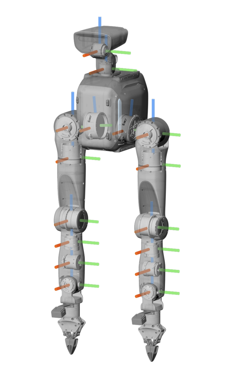
- When all joints of the Dual-Arm Robot are at zero degrees, their coordinate frames are as shown below. Red indicates the x-axis, green indicates the y-axis, and blue indicates the z-axis.
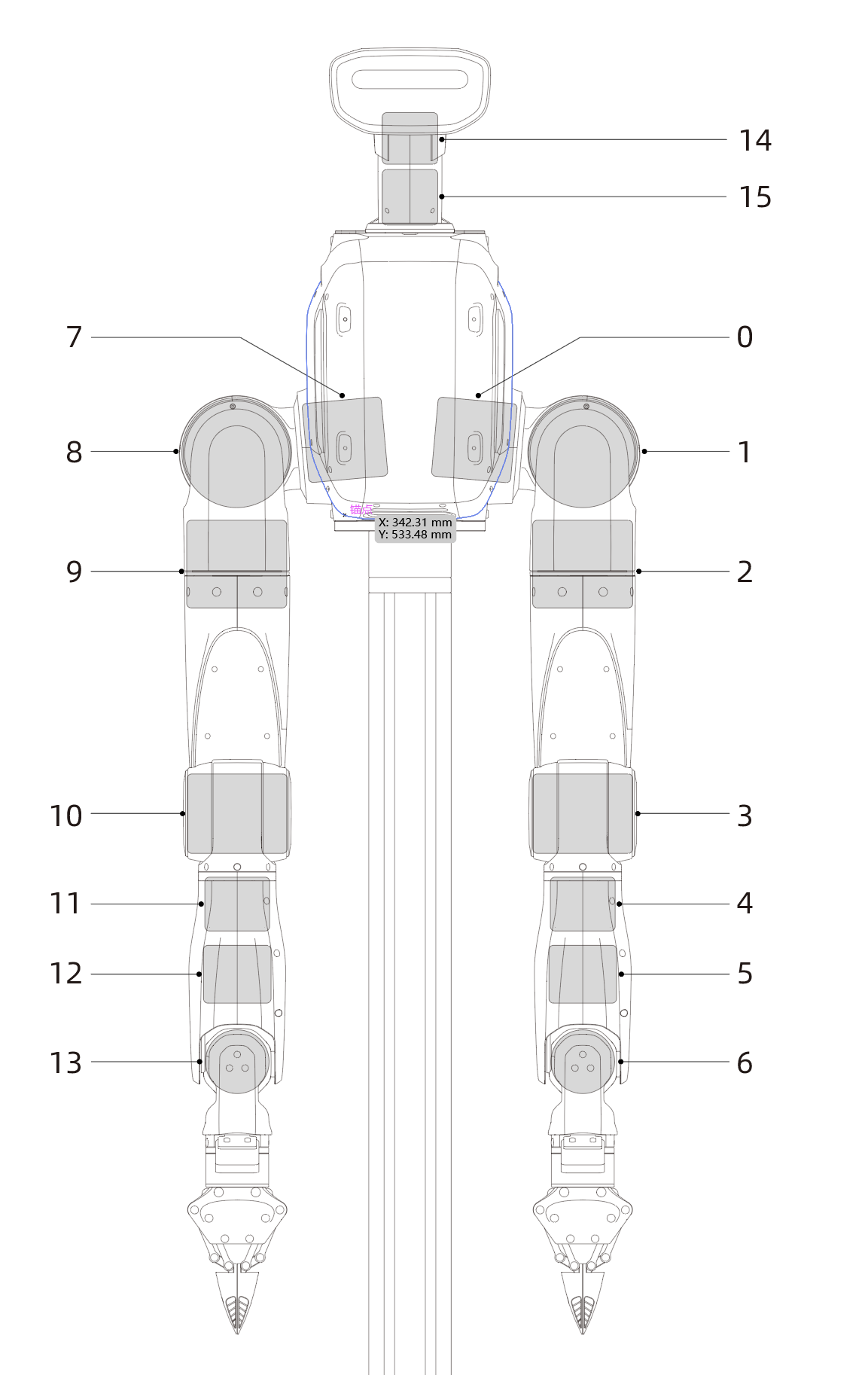
- The joint numbers and limits are shown below:
 |
|
||||||||||||||||||||||||||||||||||||||||||||||||||||||||||||||||||||||||||||||||||||||||||||||||||||||||||
2 Battery Level Check and Charging Instructions
2.1 Robot Battery Level Check and Charging
2.1.1 Checking the Robot Battery Level
Short-press the Power Button once to check the Battery Level.
2.1.2 Charging the Robot Battery
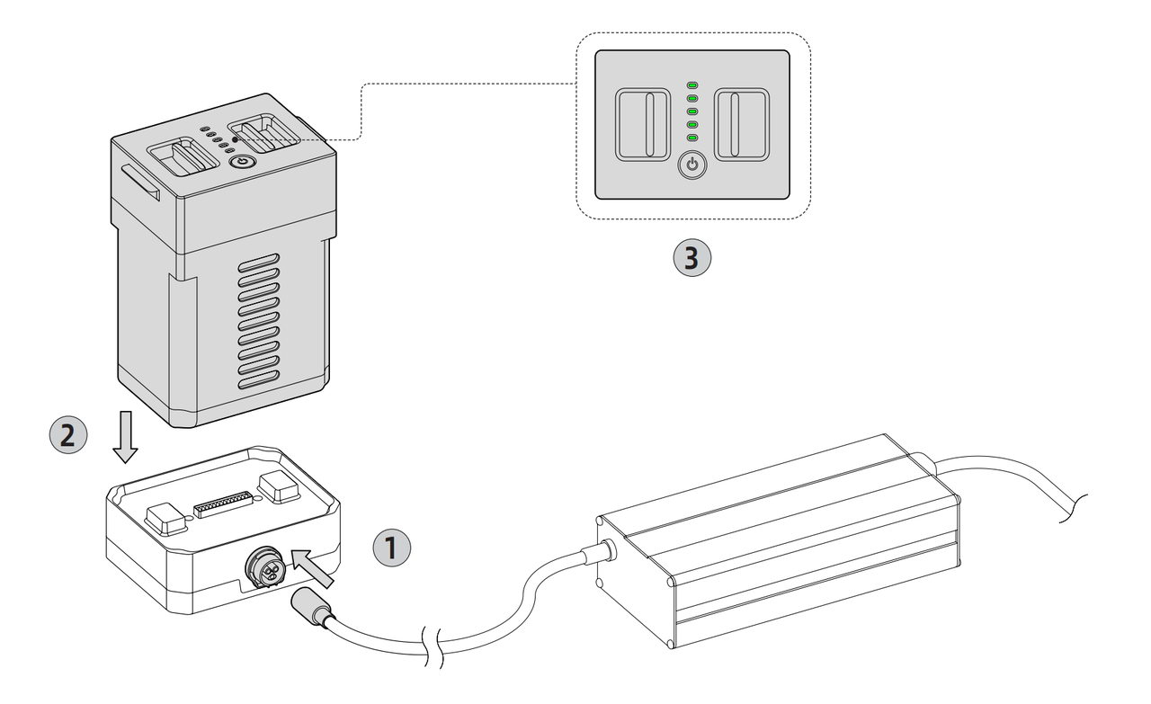
- Connect the Battery Charging Dock to the Power Adapter. Align the aviation connector with the keyed slot, and insert it.
- Insert the battery into the Battery Charging Dock. Press down until it is fully seated, then connect the Power Adapter to an AC outlet that meets the input rating marked on the Power Adapter.
- A flashing battery indicator and a steady blue Power Adapter indicator mean that charging has started. When the battery indicator and the Power Adapter indicator are both steady green, the battery is fully charged.
2.1.3 Battery and Power Adapter Indicators
| Indicator | Not Charging | Charging | Charging Complete | Charging Fault |
|---|---|---|---|---|
| Battery | Off | Green, flashing | Green, steady | |
| Power Adapter | Green, steady | Blue, steady | Green, steady | Red, flashing |
NOTICE
- If the device will not be used for an extended period, charge the battery once every three months to prevent battery damage.
- Do not leave the battery charging for an extended period. Disconnect the Power Adapter promptly after the battery is fully charged.
2.2 Remote Controller Battery Level Check and Charging
2.2.1 Checking the Remote Controller Battery Level
Press and hold the Power button below the screen to turn on the Remote Controller, then check the battery icon in the upper-right corner.
2.2.2 Charging the Remote Controller
- Connect the Type-C end of the charging cable to the Remote Controller and the other end to a 5 V/1 A power supply.
- A steady green Remote Controller indicator means that charging has started.
2.2.3 Remote Controller Charging Indicator
| Status | Not Charging | Charging/Charging Complete |
|---|---|---|
| Remote Controller Indicator | Off | Green, steady |
2.3 Mobile Base Battery Level Check and Charging (Mobile Dual-Arms Version Only)
2.3.1 Checking the Mobile Base Battery Level
The normal Mobile Base battery voltage range is 24–29.4 V. A flashing red base LED indicates low battery voltage. Charge the battery promptly.
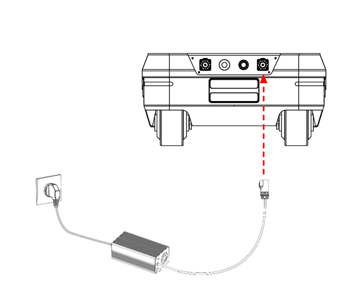
2.3.2 Charging the Mobile Base
Use the supplied 10 A charger. Insert the charger plug into the charging port at the rear of the base, connect the charger to power, and turn on the charger switch to start charging.
3 Using Your TRON 2
3.1 Operating Environment Requirements
- Electromagnetic interference: Do not operate near interference sources such as high-voltage power lines or cellular base stations.
- Wi-Fi interference: Avoid co-channel interference. If interference occurs, turn off other nearby wireless signal sources.
- Line-of-sight operation: Keep the robot in sight at all times and maintain a safety distance of at least 1 m from obstacles, people, and bodies of water.
- Temperature range: Operate between -5 °C and 40 °C. Do not use the robot outdoors in heavy fog, rain, snow, thunderstorms, or other severe weather.
- Water and dust protection: The robot is not waterproof or dustproof. Keep it away from humid, sandy, and dusty environments.
- Floor requirements: Operate on a flat, high-friction surface. Use caution on smooth surfaces.
- Safety assistance: For the Bipedal/Wheeled-Legged Configuration, use a safety tether during initial Remote-Control Mode or Developer Mode operation to help prevent falls.
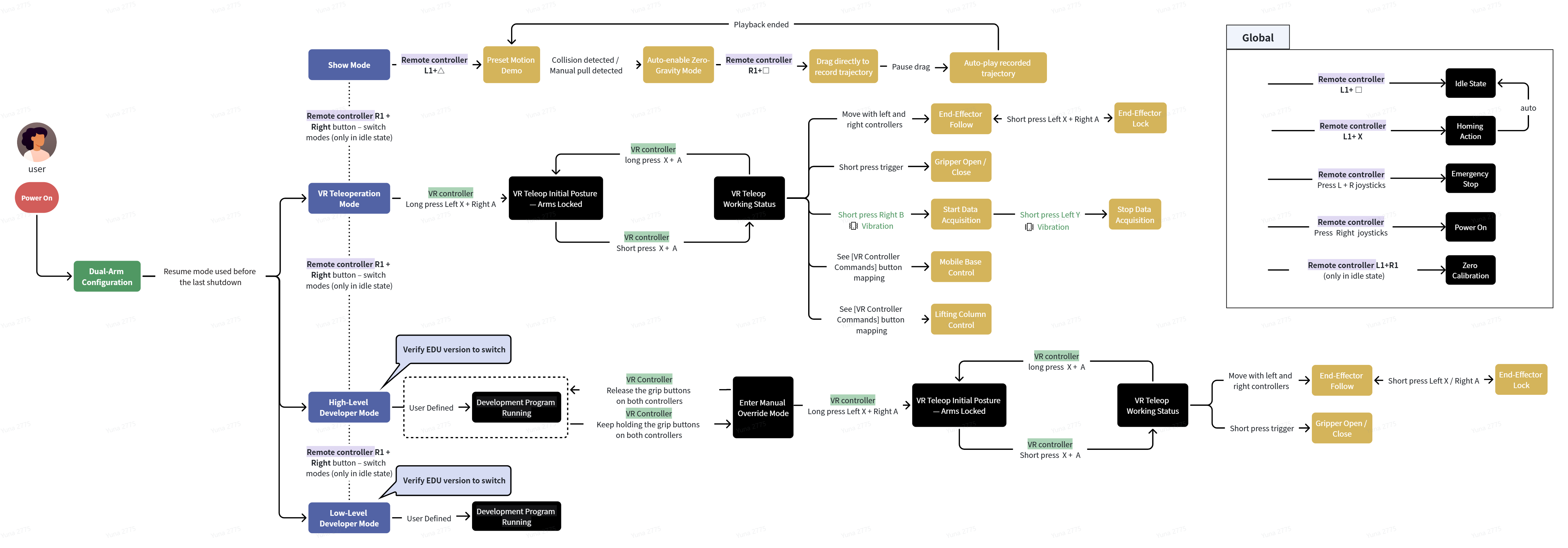
3.2 Mode Descriptions and Operating Flow
| Configuration | Mode | Description |
|---|---|---|
| Dual-Arms Configuration | Preset Motion Demo | For initial capability checks after unboxing. Use the Remote Controller to demonstrate the arms' reach and joint ranges. After the demonstration, the robot enters Demo Idle with both arms hanging naturally. |
| VR Teleoperation Mode | Uses a VR device to teleoperate the robot, primarily for data collection. At the default zero position, the upper arms hang beside the body and the forearms extend forward at 90 degrees. | |
| High-Level Development Mode | Available only on the EDU version. Supports high-level interfaces such as moveJ and servoP. The Remote Controller displays High-Level Development, and the Status Indicator is steady cyan. | |
| Low-Level Development Mode | Available only on the EDU version. Supports direct joint control through low-level Python and C++ interfaces with all control nodes disabled. The Remote Controller displays Low-Level Development, and the Status Indicator is green. |
3.3 Dual-Arm/Mobile Dual-Arms Robot Power-On/Off Procedure
3.3.1 Power-On Procedure
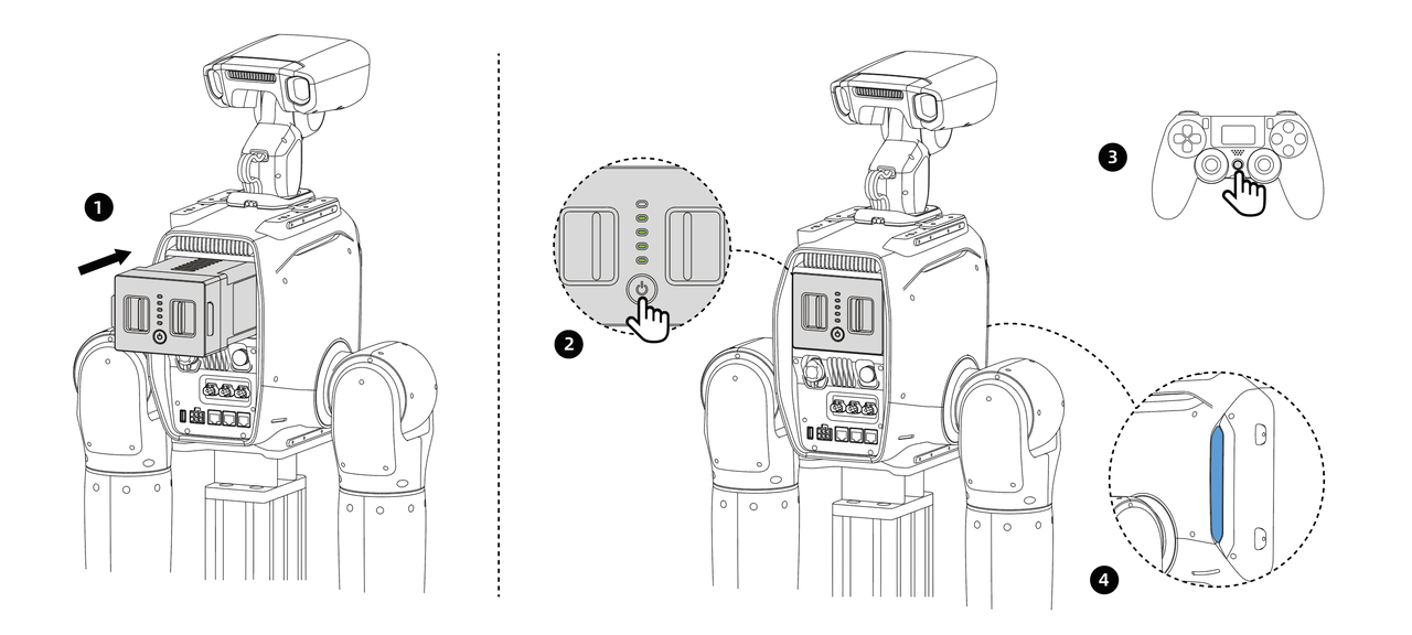
- Assemble the robot according to the installation procedure.
NOTICE: Install the robot head and connect the head-joint power and communication cables before powering on the robot.
- Insert a fully charged battery into the battery compartment and press until the latch locks. For the Fixed-stand version, connect the Power Adapter to the External Power Supply Port, then connect it to an AC outlet that meets the input rating marked on the Power Adapter. For the Mobile Dual-Arms Version, turn on the power switch at the rear of the Mobile Base.
- Short-press the robot Power Button for 0.5 seconds, then press and hold it for 3 seconds. The Battery Level Indicator turns on.
- Press and hold the Remote Controller power button for 2 seconds. The display turns on.
- Check the Status Indicator. It flashes white during startup. After approximately 20 seconds, it remains steady blue or green, indicating that startup is complete.
- Check the signal icon on the Remote Controller display. A visible signal confirms successful pairing and completes the startup procedure.
3.3.2 Power-Off Procedure
- To stop robot motion, press L1+X simultaneously in Remote-Control Mode to enter Idle. All joint motors enter torque-damping state and slowly move downward.
- For the Fixed-stand version, disconnect the External Power Supply Port. For the Mobile Dual-Arms Version, turn off the power switch at the rear of the Mobile Base.
- Short-press the robot Power Button for 0.5 seconds, then press and hold it for 3 seconds. The Battery Level Indicator and Status Indicator turn off.
- Press and hold the Remote Controller power button for 3 seconds. The display turns off.
NOTICE: Enter Idle first and allow the joint motors to return slowly. Powering off the robot directly may cause the joints to drop and damage the robot.
3.4 Status Indicator Meanings
| Event/Status | Indicator Color | Indicator Description | Frequency (seconds/time) |
| TRON2 Robot Body | |||
| Starting Up | White slow flashing | Startup self-test in progress | 1 |
| Fault Warning | Red steady | Robot fault detected | / |
| Low Battery Warning | Red flashing | Robot battery low (below 20%) | 2 |
| Critically Low Battery Warning | Red fast flashing | Robot battery low (below 5%) | 0.5 |
| Emergency Stop State | Yellow flashing | Body emergency stop button triggered | 2 |
| Preset Motion Demo | Blue-Violet | After startup or mode switching, the current mode status will be shown. | / |
| Remote-Control Mode (for Sole/wheeled) | Steady blue | After startup or mode switching, the current mode status will be shown. | / |
| VR Teleoperation Mode (for dual-arms configuration) | Steady blue | After startup or mode switching, the current mode status will be shown. | / |
| High-Level Development Mode | Steady cyan | After startup or mode switching, the current mode status will be shown. | / |
| Low-Level Development Mode | Steady green | After startup or mode switching, the current mode status will be shown. | / |
| Stair Mode (only for wheeled) | Purple dynamic | Robot is in stair mode | 2 |
| Fall (for Sole/wheeled) | Steady yellow | Robot fall detected | / |
| Off-Ground Detection (for Sole/wheeled) | Yellow breathing | Robot is in off-ground detection state | 2 |
| Mobile Base (Mobile Dual-Arms Version only) | |||
| Error | Red steady | Error occurred | / |
| Low Battery Warning | Red flashing | Battery level below 15% warning | 1 |
| Charging | Green slow flashing | Charging current greater than 1 A | 2 |
| Parking | Yellow steady | Four wheels locked in an X configuration | / |
| Normal Motion Mode | Blue steady | Standby state or straight-line motion | / |
4 Remote Controller Instructions
4.1 Powering the Remote Controller On and Off
- Power on: Press and hold the Power button for more than 2 seconds. One beep confirms startup, and the default screen appears.
- Power off: Press and hold the Power button for more than 2 seconds. One beep confirms shutdown, and the display turns off.
4.2 Display Information
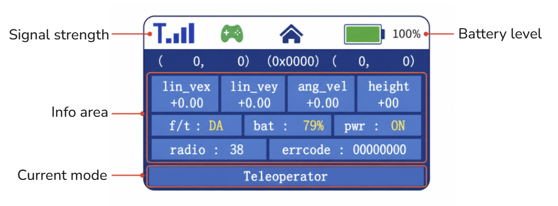
- Signal strength: No signal icon appears when the Remote Controller is disconnected. After connection, blue signal bars appear; more bars indicate a stronger signal.
- Battery Level: Shows the Remote Controller Battery Level.
- Information area: Shows the current robot mode, robot Battery Level, and motor power status.
- Current mode/status: High-Level Development / Low-Level Development / Teleoperator / Idle.
4.3 Remote Controller Buttons
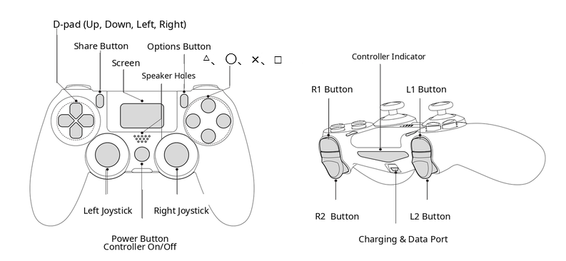
4.4 Robot Remote-Control Commands
| Function | Description | Prerequisite | Buttons | Notes |
|---|---|---|---|---|
| Mode Switching | Cycles between VR Teleoperation Mode and Developer Mode in the Dual-Arms Configuration | Idle | R1+Right | At startup, the robot retains the mode used before shutdown |
| Homing Action | Lowers both arms naturally. If safety protection is enabled, the arms avoid the tabletop. The robot enters Idle after completing the motion, and the joint motors enter torque-damping state. | VR Teleoperation Mode or High-Level Development Mode | L1+X | / |
| Enter Idle | Enters torque-damping state without a Homing Action; all joints slowly move downward | Global | L1+□ | Use only in an emergency if the Homing Action does not work |
| Emergency Stop Button | Immediately cuts power to all motor drives. Battery power and indicators remain on, and the robot will drop. | Global | Left joystick button + right joystick button | Immediately cuts motor power in any mode or state |
| Emergency Stop Release | Restores motor power | Emergency Stop state | Right joystick button | Has no effect in other states; the robot enters damping state after release |
| Zero Calibration | Recalibrates joint zero positions | Idle | L1+R1 | Required only after a Main Controller upgrade or a severe impact causes zero-position loss or position drift |
NOTICE
- An Emergency Stop immediately cuts power to all motors. Confirm that Emergency Stop is released before startup.
- Body Emergency Stop: The robot is in Emergency Stop state when the Emergency Stop Button is pressed and exits it when the button is released. Power-cycle the robot after Emergency Stop Release.
- Remote Emergency Stop: Press both joystick buttons simultaneously to trigger Emergency Stop. Press the right joystick button to release it, then wait several seconds for the robot to recover automatically.
5 VR Device and Dual-Arm Teleoperation Instructions
5.1 VR Controller Buttons
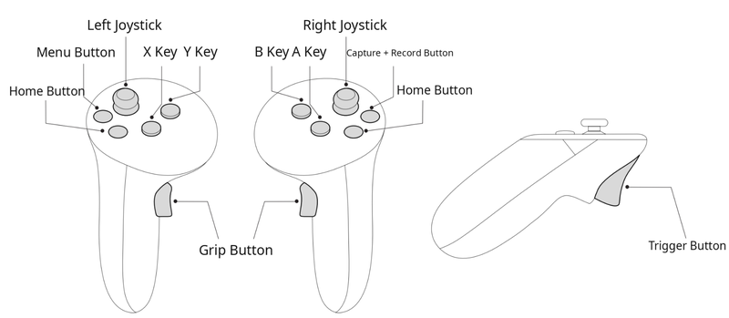
5.2 VR Device Commands
5.2.1 Dual Arms
| Function | Description | Prerequisite | Button |
|---|---|---|---|
| Start VR Teleoperation | Moves the arms from Idle to the initial teleoperation zero position and performs Zero Calibration for the grippers | Robot is in VR Teleoperation Mode | Press and hold the X button on the left controller and the A button on the right controller simultaneously for more than 1 second |
| Return to Initial Teleoperation Position | Returns the arms to the initial zero position with the elbows bent forward at 90 degrees | VR teleoperation operating state | Press and hold the X button on the left controller and the A button on the right controller simultaneously for more than 1 second |
| End-Effector Tracking | The arm end effectors track the left controller and right controller | Initial teleoperation position or operating state | None |
| End-Effector Lock | Locks either arm during teleoperation. At the zero-position lock, press the X button on the left controller and the A button on the right controller simultaneously. During teleoperation, press X to pause/resume the left arm or A to pause/resume the right arm. | Initial teleoperation position or operating state | Short-press X on the left controller or A on the right controller |
| Gripper Control | Short-press to close or open the corresponding gripper | Initial teleoperation position or operating state | Trigger button (T button) on the left controller/right controller |
| Start Data Collection | Starts recording teleoperation data. The controllers vibrate and the data platform status updates. | VR teleoperation operating state | B button on the right controller |
| Stop Data Collection | Stops recording teleoperation data. The controllers vibrate and the data platform status updates. | VR teleoperation operating state | Y button on the left controller |
5.2.2 Mobile Base
| Function | Description | Prerequisite | Button |
|---|---|---|---|
| Base Mode Selection | Selects Ackermann Mode or Diagonal Movement Mode | VR teleoperation operating state | Ackermann Mode is the default. Hold the joystick on the right controller for 1 second for Diagonal Movement Mode; hold the joystick on the left controller for 1 second for Ackermann Mode. |
| Move Forward | Moves the robot forward | VR teleoperation operating state | Push the joystick on the left controller forward |
| Move Backward | Moves the robot backward | VR teleoperation operating state | Pull the joystick on the left controller backward |
| Ackermann Steering | Rotates the drive wheels to turn the base in Ackermann Mode | VR teleoperation operating state | Push the joystick on the right controller left/right in Ackermann Mode |
| Diagonal Movement | Keeps the base orientation fixed while moving diagonally left/right | VR teleoperation operating state | Push the joystick on the right controller left/right in Diagonal Movement Mode |
| Speed Adjustment | Adjusts Mobile Base speed in proportion to joystick travel | VR teleoperation operating state | Push the joystick on the left controller forward/backward; greater travel produces greater speed |
| Parking | Locks all four steering wheels in an X pattern for extended stationary operation | VR teleoperation operating state | Hold the Grip button on the left controller and the joystick on the right controller for 1 second |
| Emergency Stop | Immediately stops the Mobile Base on a Mobile Dual-Arms Version | VR teleoperation operating state | Press the joystick buttons on the left controller and right controller simultaneously, or press both Remote Controller joystick buttons simultaneously |
5.2.3 Lifting Stand
| Function | Description | Prerequisite | Button |
|---|---|---|---|
| Raise | Raises the robot using the stand | VR teleoperation operating state | Hold the Grip button on the right controller and push the joystick on the left controller forward |
| Lower | Lowers the robot using the stand | VR teleoperation operating state | Hold the Grip button on the right controller and pull the joystick on the left controller backward |
| Return to Zero | Returns the stand to its uppermost zero position for battery removal | VR teleoperation operating state | Hold the Grip button on the right controller and the joystick on the left controller for 1 second |
5.3 Preparing for Teleoperation
5.3.1 Dual-Arm Zero Calibration
NOTICE
- Perform Zero Calibration only after a Main Controller upgrade or if a severe impact causes zero-position loss or position drift.
- On the Mobile Dual-Arms Version, raise the robot to its highest position before Zero Calibration.
- After Zero Calibration, wait approximately 5 seconds while the robot refreshes the new zero-position data before performing another operation.
- Press
L1+Xto ensure that both arms are in Idle and hanging naturally. - Press
L1+R1on the Remote Controller to start automatic Zero Calibration. When calibration is complete, both arms should hang naturally. - If the Status Indicator turns red during calibration, Zero Calibration failed. Try again.
5.3.2 Switching TRON 2 to VR Teleoperation Mode
After the robot starts, switch the Remote Controller to Idle. Modes can be switched only in Idle. Press R1+Right repeatedly until the Remote Controller displays Teleoperator. The robot is now in VR Teleoperation Mode, and its Status Indicator remains steady blue.
5.3.3 Starting the Teleoperation App on the VR Device
NOTICE: Do not remove the sensor cover sticker before use. Removing it may cause the headset to enter sleep mode frequently.
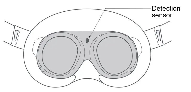
- Turn on the VR device and connect to the TRON 2 Wi-Fi network,
TRON2A_XXX_2.4GorTRON2A_XXX_5G. Enter password12345678.
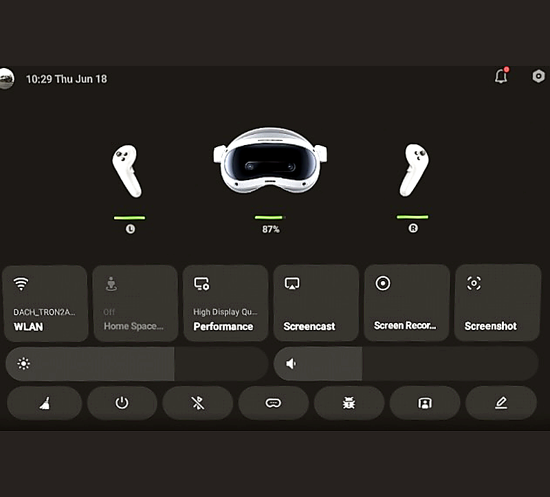
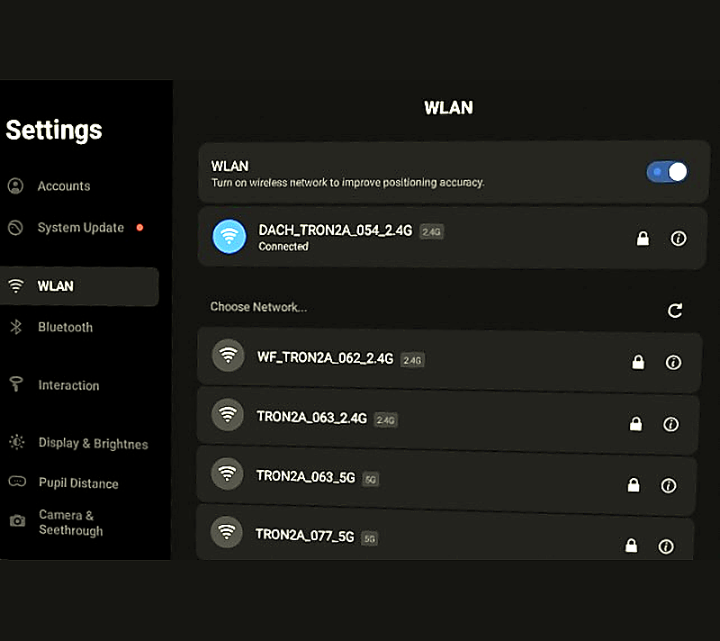
-
In Library, select the installed
Limx_teleopapp. -
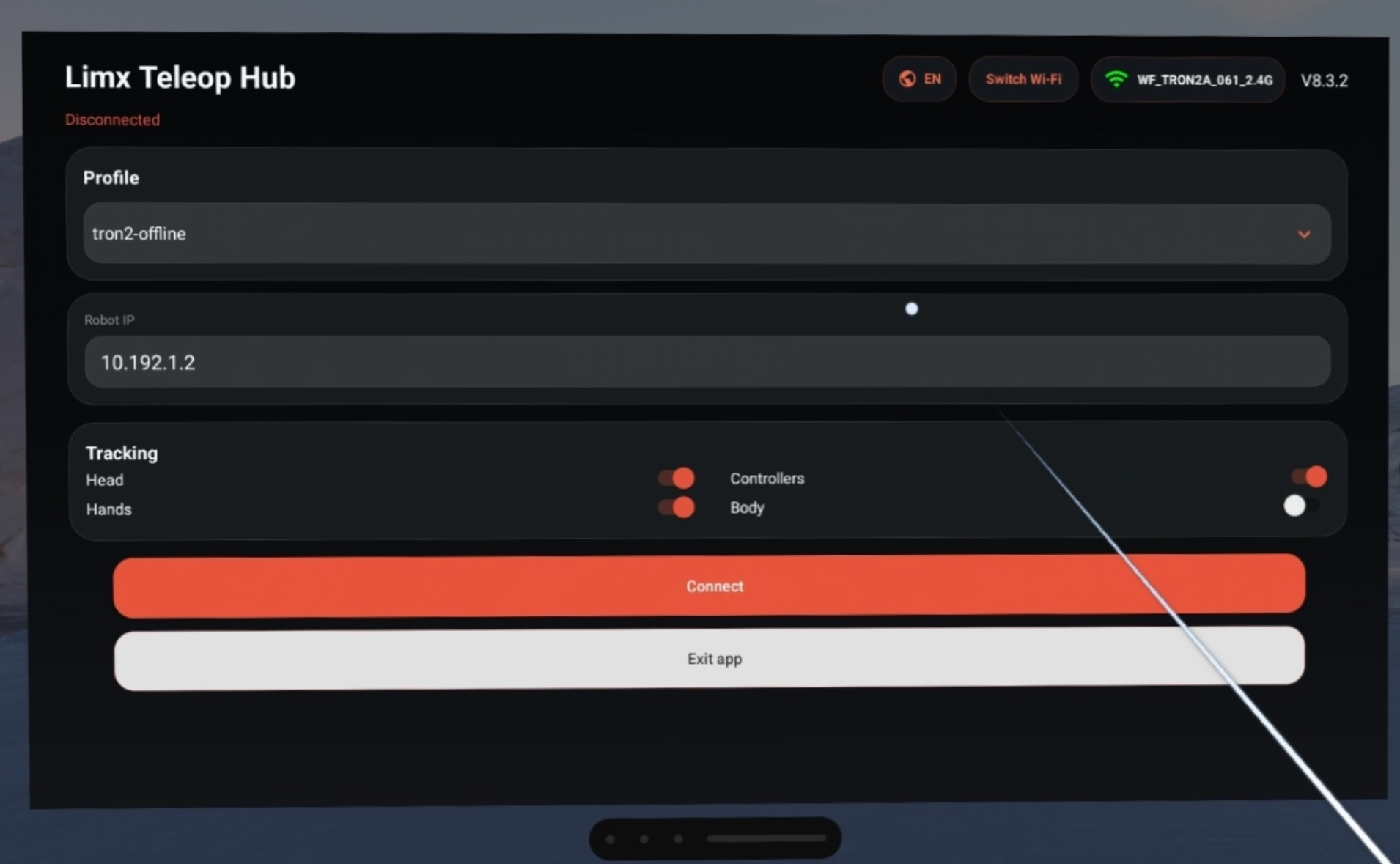
Select
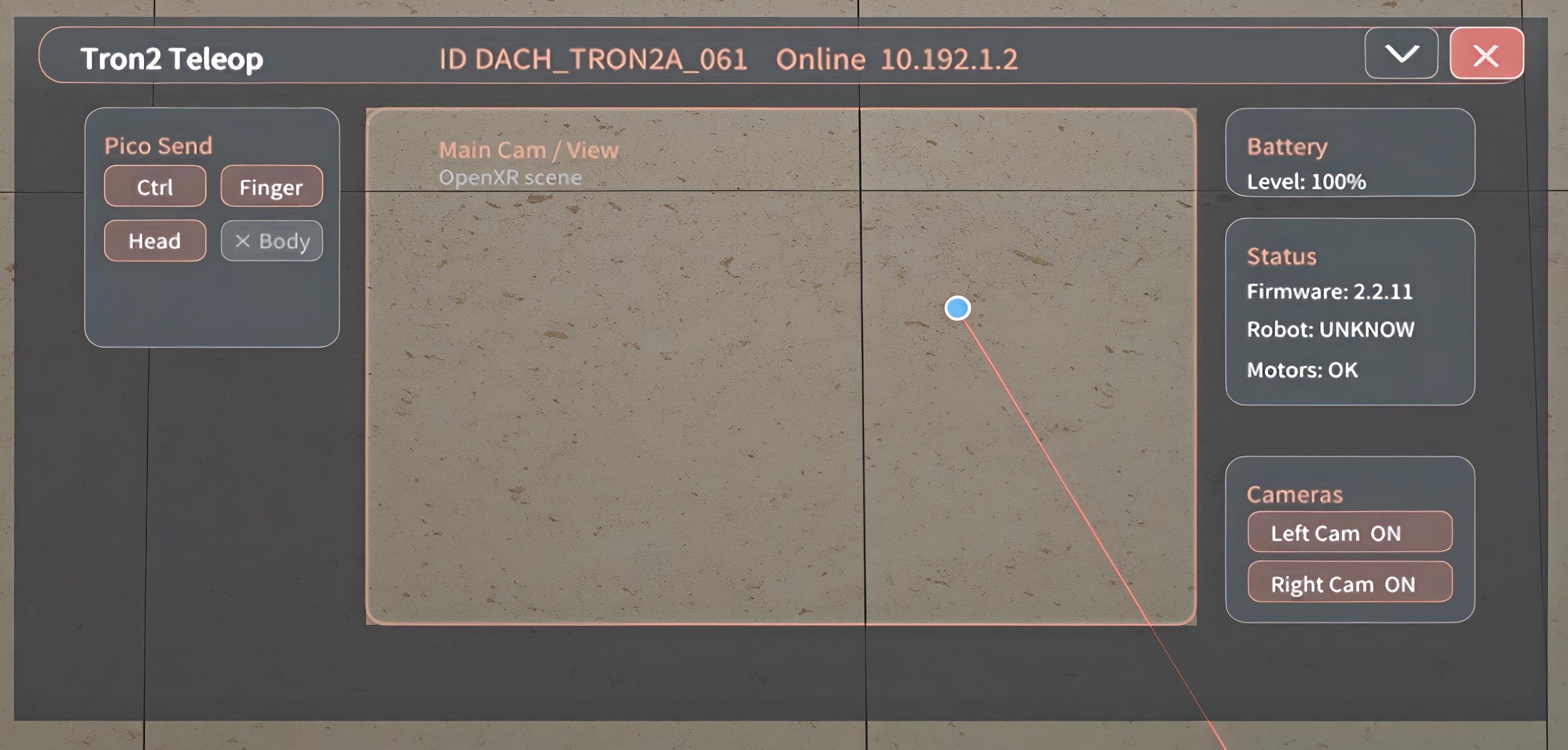
tron2-offlineand enter robot IP address10.192.1.2. Keep the default tracking settings with Head, Controller, and Hand selected. Select Connect to enter the TRON 2 teleoperation operating state. The default perspective appears as shown below.
NOTICE: If prompted to enable body tracking, select No.
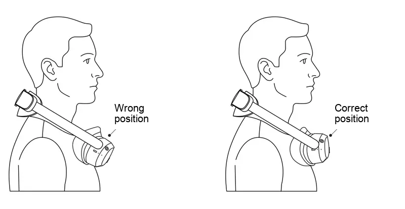
- Hang the VR headset horizontally around your neck as shown below, and hold the left controller and right controller.
5.4 Using Teleoperation
5.4.1 Entering the Ready State
Press and hold the X button on the left controller + A button on the right controller simultaneously for 1.0 seconds to initiate the return-to-zero motion. When the motion is complete, both arms are in the teleoperation ready state, with the forearms extended forward at 90 degrees.
5.4.2 Starting Teleoperation
Hold the left controller and right controller with your arms in approximately the same pose as the robot arms and both controllers level and pointing forward. Short-press the X button on the left controller + A button on the right controller simultaneously for approximately 0.2 seconds to unlock the arms and enter the teleoperation operating state.
5.4.3 Returning Both Arms to the Ready State
Press and hold the X button on the left controller + A button on the right controller simultaneously for 1.0 seconds to return both arms to the initial forward-ready position.
5.4.4 Unlocking Both Arms
After a return-to-zero motion, both arms are locked by default. Short-press the X button on the left controller + A button on the right controller simultaneously for approximately 0.2 seconds to unlock them. The arm end effectors then track the controller positions.
5.4.5 Pausing/Resuming One Arm
Use this function to correct a large difference between the operator's arm pose and the robot arm pose.
- Short-press
Xto pause the left arm; short-press it again to resume. - Short-press
Ato pause the right arm; short-press it again to resume.
When resumed, the arm continues moving from the paused position.
5.4.6 Operating the Grippers
Short-press the Trigger button on the left controller/right controller to open the corresponding gripper. Press it again to close the gripper.
5.4.7 Controlling the Mobile Base and Lifting Stand (Mobile Dual-Arms Version Only)
The Mobile Base and Lifting Stand can now be controlled using the VR device commands described above.
6 Robot Network Connection
6.1 Connecting a Computer to the Robot by Ethernet
- Connect the Gigabit Ethernet port on the rear of the robot to the computer with an Ethernet cable.
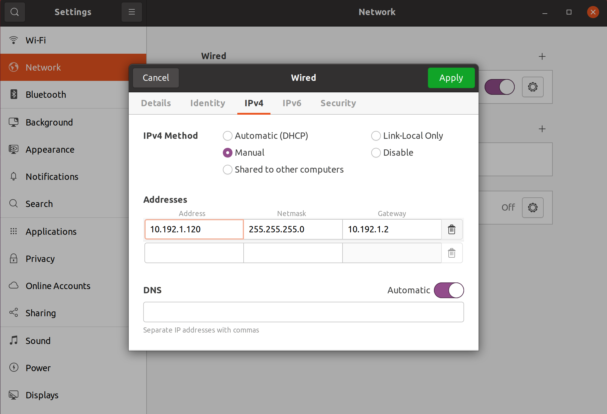
- Set the computer IP address to the same subnet as the robot. The robot IP address is
10.192.1.2; for example, set the computer IP address to10.192.1.120.
6.2 Connecting a Computer to the Robot by Wi-Fi
- After the robot starts, connect the computer to a robot Wi-Fi network. The SSID format is typically
XXXX_TRON2A_XXX_2.4GorXXXX_TRON2A_XXX_5G. - Enter Wi-Fi password
12345678.
6.3 Connecting the Robot to the Internet
- After connecting the computer to the robot, open the Robot Management page at http://10.192.1.2:8080.
- Select the Wi-Fi icon on the right and enter the external network's Wi-Fi band, SSID, Wi-Fi password, and router administrator password.
7 Software Upgrade
7.1 Upgrading Robot Firmware
Open the Robot Management page in a browser and select a previously downloaded robot software package. Follow these steps:
-
Connect and configure the IP address:
- Connect the computer to the robot.
- Run
ping 10.192.1.2in a shell to verify the connection.
-
Open the Robot Management page: Enter http://10.192.1.2:8080 in the browser address bar.
-
Select and upgrade the software:
- Go to the LimX Dynamics website > Download Center at https://www.limxdynamics.com/en/downloads. Select TRON 2, then download the required firmware type and version.
-
On the Robot Management page, open Version Management, select the firmware type, select Choose File, and upload the firmware package. After the upload completes, select Upgrade and wait for the process to finish.
-
NOTICE: Motor-drive firmware requires two upgrade passes for all configurations. First, select all motors, choose the downloaded TRON 2 Motor Driver Firmware package, and select Upgrade. Then select all motors again, choose the downloaded TRON 2 Motor Driver Firmware Supplementary Package, and select Upgrade.
-
NOTICE: The robot restarts automatically after some firmware upgrades.
7.2 Upgrading the VR Device App
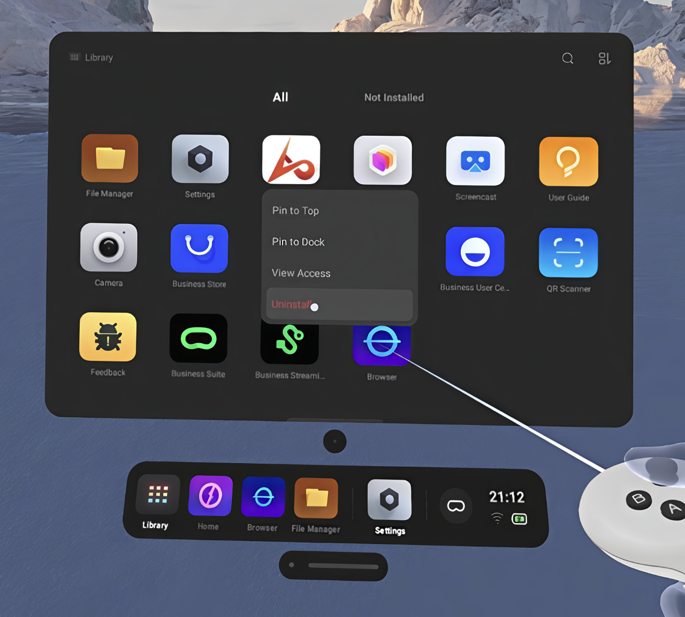
1.Delete the installed app before upgrading.
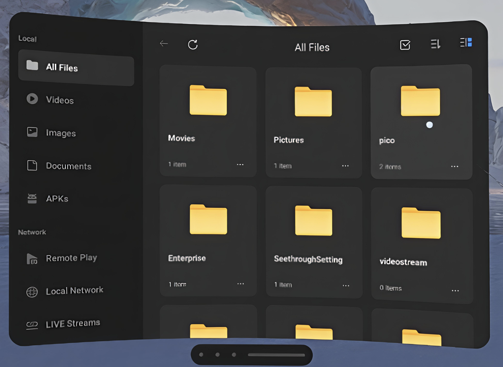
2.Connect the PICO device to the computer with a Type-C cable. Move the downloaded PICO update package to the pico folder in the PICO 4 Ultra internal shared storage.
3.Use the VR controller to open the pico folder.
4.Select the software package to install.
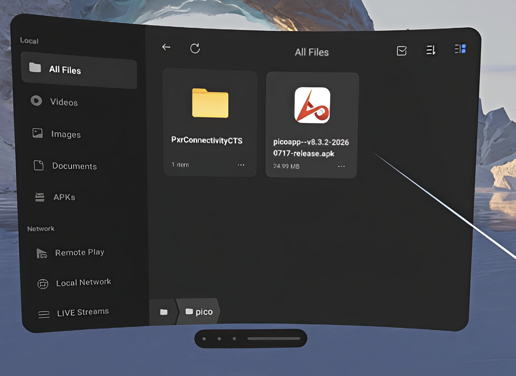
Select Install.
8 Exporting Logs
- Connect to the robot Wi-Fi network using password
12345678. - Enter http://10.192.1.2:8090 in the browser address bar to open the log management page.
- Export the log and bag files for the time when the issue occurred.
9 Routine Care and Maintenance
9.1 Cleaning and Storage
- Clean the robot surface regularly with a clean microfiber cloth, especially after operation in a dusty environment.
- Store and transport the robot in a case designed for TRON 2 to protect it from impact and vibration.
9.2 Inspection and Maintenance
- Exterior maintenance: Remove dust from the joints and check for loose screws.
- Software updates: Install official firmware updates promptly to address potential system vulnerabilities and improve motion-control algorithms.
- Battery pack: Charge the battery to 50%–60% before storage. Do not store it fully charged or depleted. Recharge it to the same level every three months.
- Remote Controller: Keep the ports clean, ensure that the joysticks are not subjected to external force during storage, and periodically check the controller for signal interference.