Version History
| Version | Revision Date | Modified Content | Remarks |
|---|---|---|---|
| V1.0 | 20250609 | Sort out the information of the Sensor Expansion Kit and officially release it externally | |
| V1.1 | 20250725 | In the part of setting up the development board environment, install ROS Noetic and replace the local address | |
| v2.0 | 20250808 | Modify the abnormal error report after "git clone https://github.com/limxdynamics/tron1-ss # Mapping, localization, and navigation code | |
| v2.1 | 20250905 | 1. In the "Material Preparation" section, add computer performance requirements 2. In the "Setting up the Development Board Environment" section, set up Add GTSAM Installation Verification 3. Full text readability optimization |
|
| v2.2 | 20251013 | 1. In the ROS environment installation section, add the installation of TEB and global planner planners. |
|
| v2.3 | 20260528 | Add radar and camera structural parameters for the Tron1 perception suite |
|
| v2.4 | 20260901 | 1. In the Environment Installation section, add D435 depth camera installation. 2. In the Examples section, add D435 depth camera usage. 3.Add mid360s support. |
tips:
The SDK documentation for the Sensor Expansion Kit is mainly used by users who have purchased the Sensor Expansion Kit ( including LiDAR and depth cameras ) to quickly implement examples such as 3D mapping, re-localization, navigation, and obstacle avoidance through this documentation .
1. Material Preparation
1.1 Hardware Preparation
| Serial Number | Material Name | Description |
|---|---|---|
| 1 | TRON1 Robot + Sensor Expansion Kit | |
| 2 | Developer Computer:Recommended Hardware with 16GB or more RAM and i7 or higher level CPU | - During the 3D mapping process, the user's computer will be used to process point cloud data and edit maps; this places certain requirements on the performance of the user's computer. If the above conditions are not met, it may result in the inability to edit or save point cloud data; - It is recommended not to use a virtual machine. |
| 3 | RJ45 Ethernet Cable |
1.2 Development Environment
-
The example code in this document is developed based on Ubuntu 20.04 operating system, ROS 1 (noetic) version, please prepare in advance the Development Environment.
-
3D mapping and relocalization require the use of rviz, a tool built into ROS, to view maps and point clouds. You can first download and prepare the files below to your local machine.
1.3 Structural parameters of radar and camera
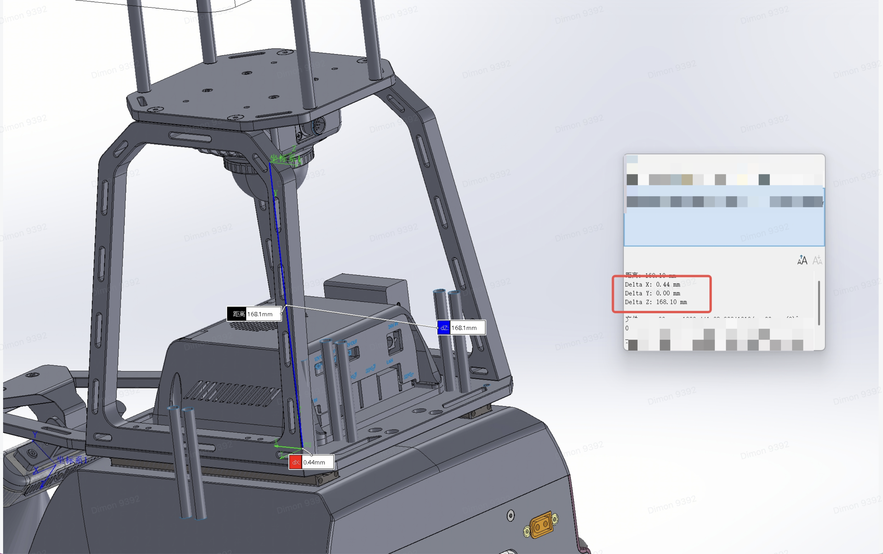
1.3.1 Radar based on the structural parameters of the robot body Base (IMU)
x:-0.00044m
y:0
z:0.1681m
Angle: pitch rotation 180° (just upside down)
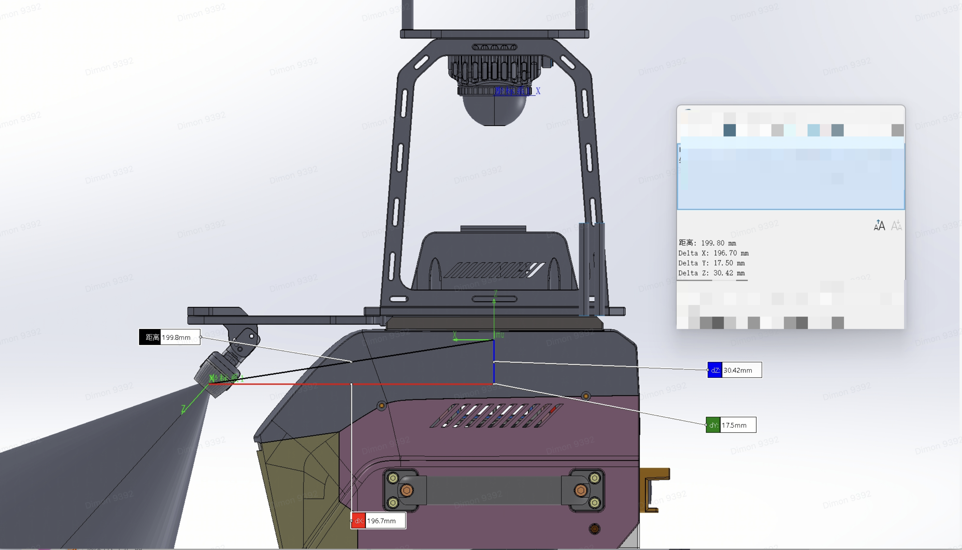
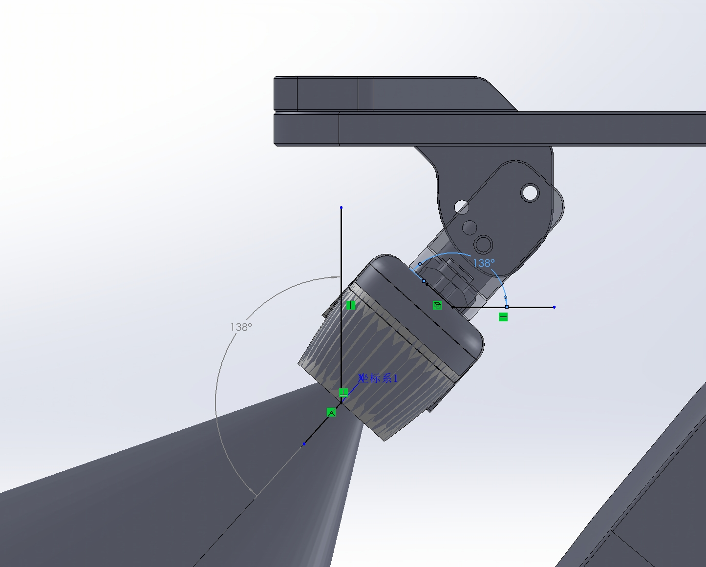
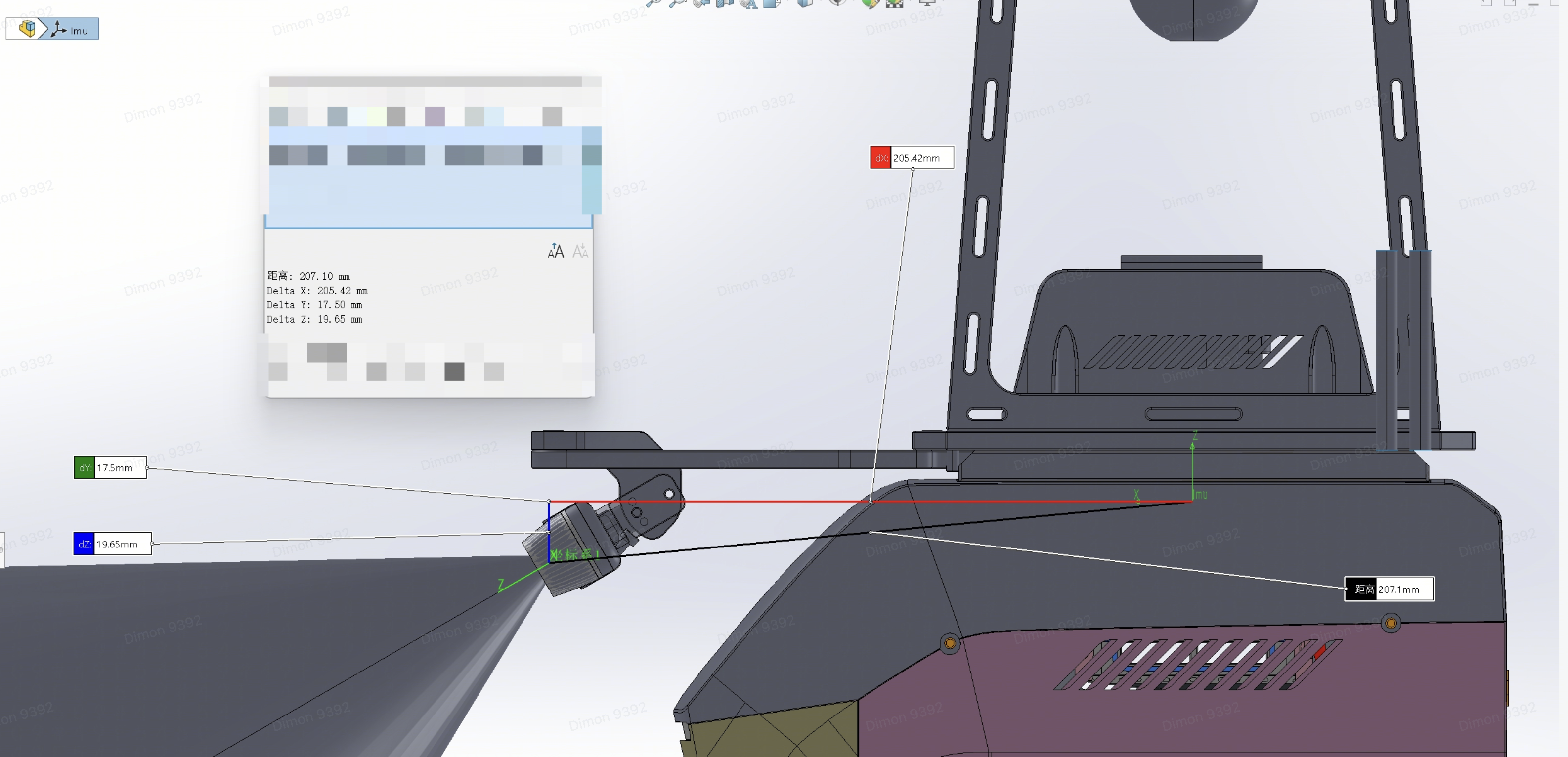
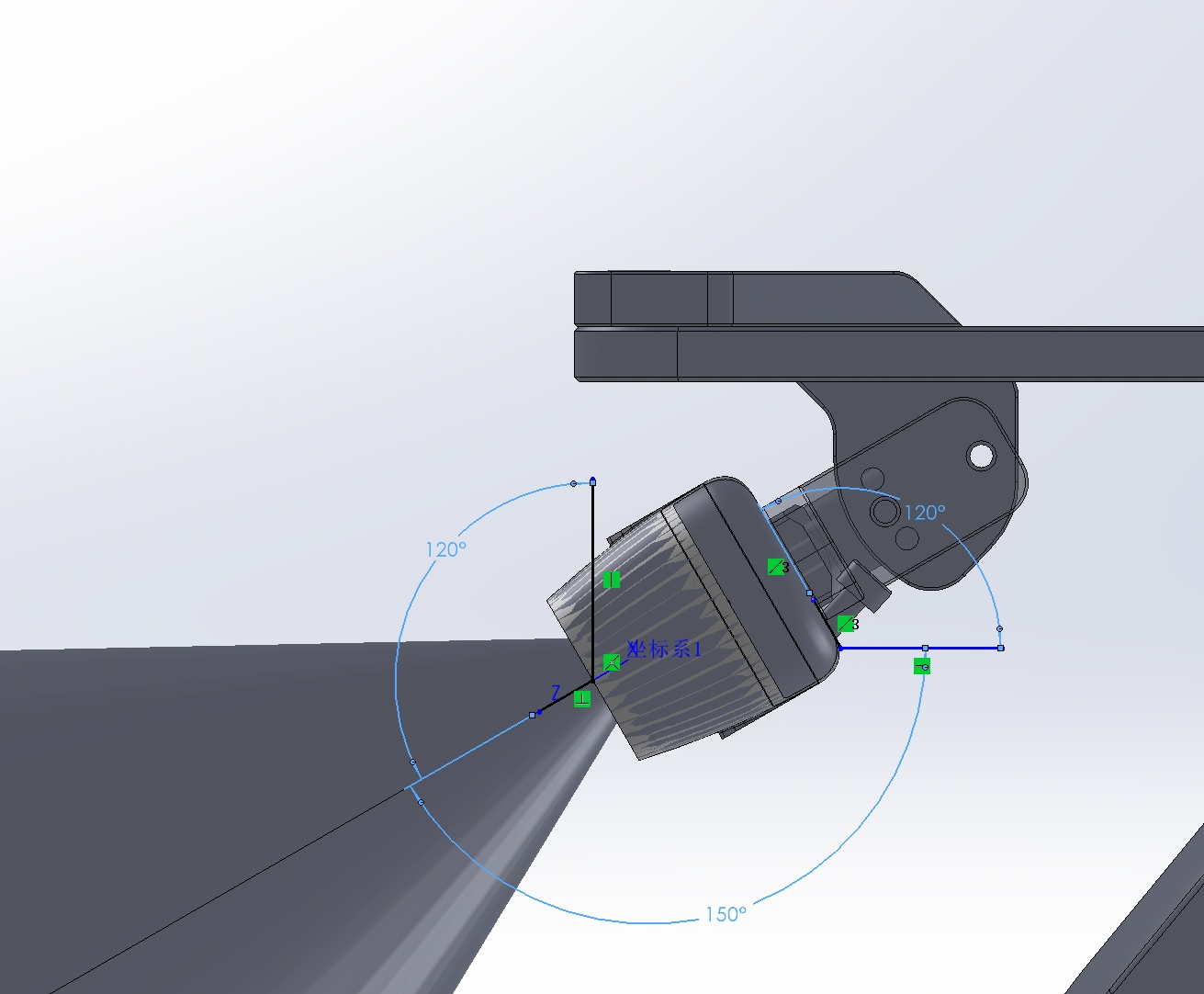
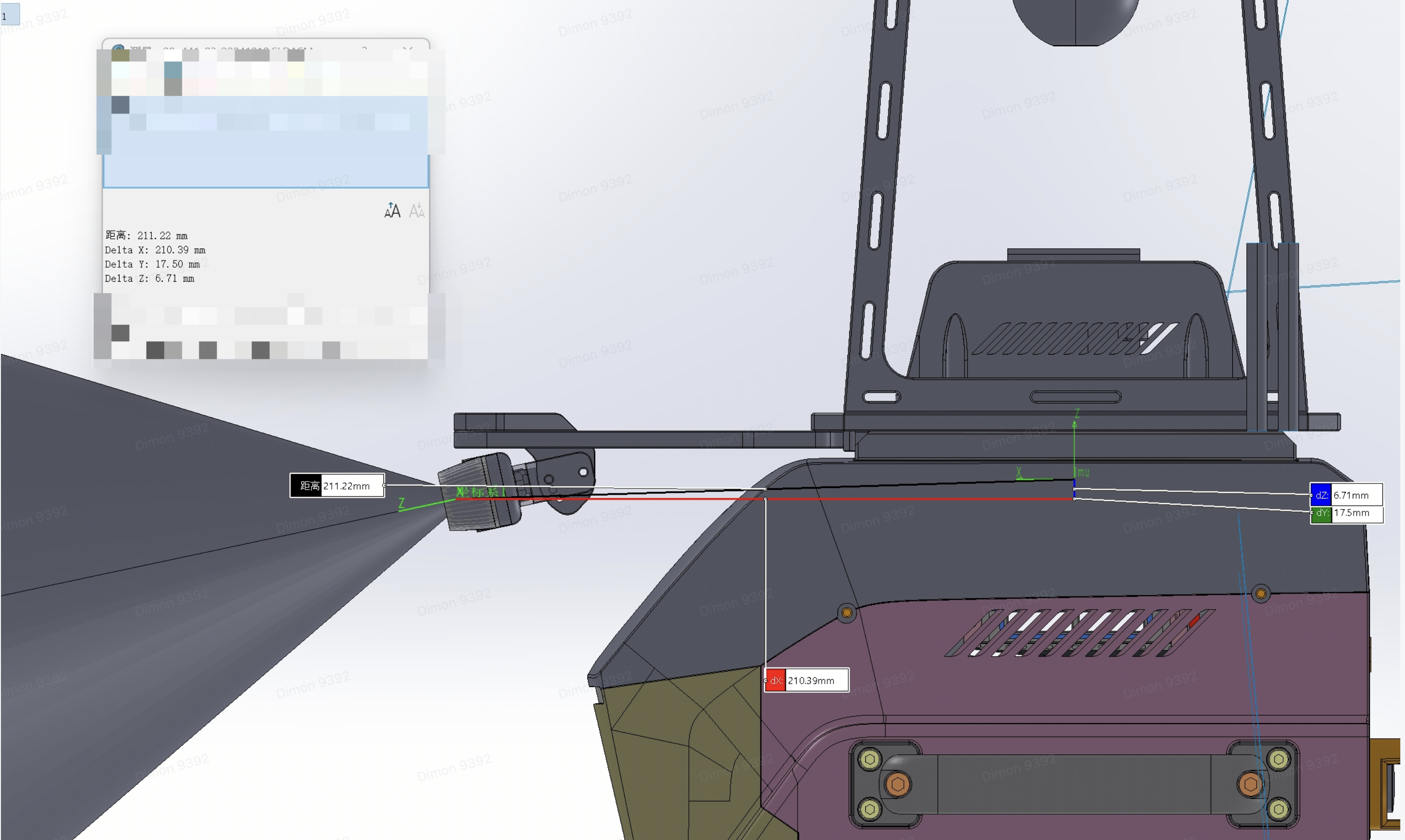
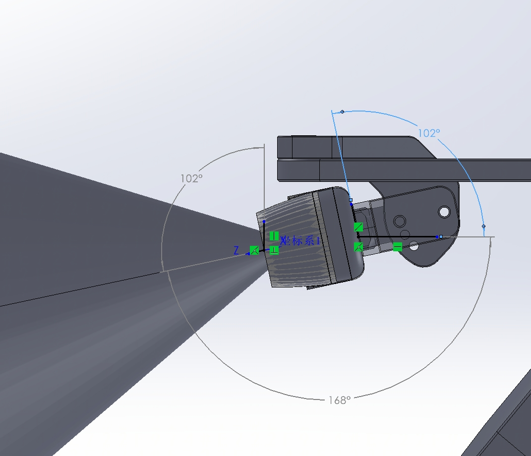
1.3.2The camera is based on the coordinate and angle parameters of the machine body Base (with a total of three adjustable angles)
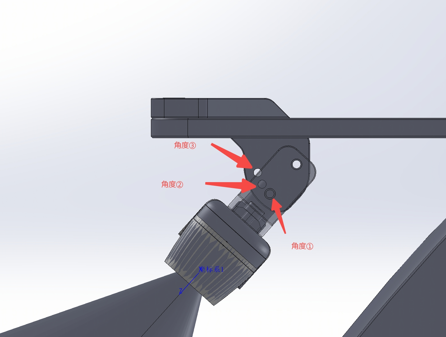
Angle ①:
Relative to the body IMU coordinates: x: 0.1967; y: -0.0175; z: -0.03042
Angle: 138° (as shown in the figure)
Angle ②:
Relative to the body IMU coordinates: x: 0.20542; y: -0.0175; z: -0.01965
Angle: 120° (as shown in the figure)
Angle ③:
Relative to the body IMU coordinates: x: 0.21039; y: -0.0175; z: -0.00671
Angle: 102° (as shown in the figure)
2. Algorithm Overview
In this project, we divide the code into two parts: perception and navigation.
2.1 Perception Algorithm
First, the perception algorithm uses FAST-LIO2. FAST-LIO2 is a LiDAR-Inertial Odometry (LIO) framework based on a tightly coupled iterated Kalman filter (IEKF), developed by the Mars Lab at the University of Hong Kong for high-precision, high-robustness real-time localization and mapping (SLAM). Its core idea is to deeply fuse raw LiDAR point cloud data with IMU data, and jointly optimize state estimation and map updates. Without extracting feature points, it directly registers raw points to the global map, thereby improving the system's ability to perceive subtle environmental structures and its localization accuracy.
The two key innovations of FAST-LIO2 include:
- Removal of the feature extraction module: Unlike FAST-LIO, FAST-LIO2 no longer relies on extracting geometric features such as edges or planes. Instead, it directly uses raw point clouds for registration and state estimation, thereby preserving more environmental details and improving mapping accuracy and robustness.
- Incremental k-d tree (ikd-Tree) map structure: FAST-LIO2 introduces an efficient dynamic map management mechanism—ikd-Tree—which supports incremental map updates and dynamic balancing, significantly improving real-time performance and memory efficiency in large-scale environments.
The system architecture mainly consists of four modules:
- Data acquisition and preprocessing module: Responsible for synchronously receiving LiDAR and IMU data, and performing preprocessing operations such as time alignment and de-distortion.
- State estimation module: Predicts the system state based on IMU data, and fuses LiDAR observations through an iterated Kalman filter to achieve high-precision state estimation.
- Map construction and update module: Registers newly observed point clouds into the global map, and uses ikd-Tree to achieve incremental map updates and maintenance.
- Optimization and loop closure detection module (optional): Further improves map consistency, suitable for long-duration mapping tasks.
FAST-LIO2 is applicable to a variety of complex environments, including indoor and outdoor dynamic scenes, UAVs, AGVs (automated guided vehicles), and other mobile platforms. It has the advantages of high computational efficiency, strong robustness, and strong adaptability, and is one of the current mainstream LiDAR SLAM solutions.
2.2 Navigation Algorithm
The navigation algorithm is implemented based on ROS move_base.
The ROS move_base node internally maintains a "global costmap" and a "local costmap". The global costmap is usually initialized by a static PGM/YAML map loaded by map_server, and thereafter is almost never updated. It is used to provide macro-environmental information to the global planner. The local costmap is centered on the robot's current position, takes real-time sensor data such as LiDAR and depth cameras as input, and is continuously updated in a rolling manner by the costmap_2d node at a frequency of 5–20 Hz to reflect suddenly appearing or moving obstacles.
After receiving a move_base_simple/goal or an Action goal, move_base first writes the goal into the global planner plugin (default navfn, based on Dijkstra). The global planner performs an A* or Dijkstra search on the global costmap, outputs a rough path from the current pose to the target pose, and sends it in the form of nav_msgs/Path into the input buffer of the local planner.
The local planner plugin (such as dwa_local_planner) then performs a "trajectory sampling-scoring" loop on the local costmap: it discretely samples multiple sets of velocities in the velocity space (v, ω), uses the kinematic model to forward-simulate trajectories within 2–3 s, scores each trajectory with weights such as "obstacle avoidance distance", "deviation from the global path", and "velocity smoothness", selects the highest-scoring trajectory, and publishes its corresponding linear velocity v and angular velocity ω as geometry_msgs/Twist to the cmd_vel topic, usually with a period of 10–20 ms.
When the sensor finds that the path ahead is blocked and the local planner cannot output a valid velocity for several consecutive cycles, the move_base state machine enters the RECOVERY state and sequentially calls the loaded recovery behavior plugins: first clears the obstacle layer of the local costmap, then rotates 360° in place to rescan. If it still cannot pass, it more aggressively clears both the global and local costmaps and rotates again. If all recovery behaviors fail, it returns ABORT to the upper-level node through the Action interface along with a "path blocked" reason code.
The entire framework adopts a plugin mechanism. The global planner, local planner, and recovery behaviors all inherit from the virtual base classes of nav_core. Users only need to modify the plugin names in the parameter file to replace navfn with global_planner, replace dwa_local_planner with teb_local_planner, or add custom recovery behaviors, without recompiling the move_base core.
2.3 Data Flow Analysis
The data flow architecture is shown in the figure below:
Real-time point cloud + IMU
    ↓
FAST-LIO2 odometry
    ↓
Keyframe detection → Scan Context loop closure candidates
    ↓
Quatro coarse registration (fast global registration)
    ↓
Nano-GICP fine registration (ICP optimization)
    ↓
Pose correction → Publish localization result
The LiDAR collects point clouds. The FAST-LIO2 algorithm fuses IMU and point clouds in real time for localization and mapping. The navigation module slices the 3D point cloud into 2D laser data for obstacle detection. After building the costmap, the DWA/TEB algorithm performs path planning and obstacle avoidance, ultimately enabling the robot to achieve autonomous localization, mapping, and navigation.
3.Set up the environment
3.1 Hardware Setup
After receiving the Sensor Expansion Kit, first refer to the Quick Start Guide TRON 1-Quick Start Guide for Sensor Expansion Kit.pdf to install it on the robot expansion platform, insert the network cable into the robot's network port, plug the power cord into the robot's external 24V voltage output port, turn on the device, wait about 4 seconds, the network port light of the development board lights up, and the radar vibrates, indicating that the kit has been successfully powered on.
Note:
To ensure smooth network connectivity during user development, we recommend that users first connect the network cable shown in the figure below, which is connected to the TRON1 ontology, to the computer, and then connect the computer to a wireless network (i.e., unplug the network cable from port 7 and plug it into the computer's wired network port). Otherwise, the computer will be unable to connect to the extranet during development.

提示:
Note: When installing the Sensor Expansion Kit, it should follow the sequence of being inserted into the slide rail from the front to the rear of the TRON body; otherwise, the slide rail and housing will be damaged.
3.2 Development Board Environment Setup
3.2.1 Set IP Address
Note: The IP Address **set at the factory of the Sensor Expansion Kit development board is:
10.192.1.3.
Keep the user computer's IP address, robot's IP address, and development board's IP address within the same local area network, i.e., 10.192.1.x .
3.2.2 End point SSH connection to the development board
When the IP Address update is completed and the Sensor Expansion Kit is powered on, connect the user's computer to the robot's WiFi (password: 12345678), and execute the following commands to set up the environment.
ssh guest@10.192.1.3 #Password:123456
If you encounter the error shown in the figure below, run the code in "remove with" and then reconnect via SSH.

3.2.3 Development Board Connects to the Network
When setting up the environment, the development board needs to be connected to the network, which can be achieved by executing the following commands on the user's computer (this method does not apply to hidden wireless networks).
ssh guest@10.192.1.3
#Password:123456
#If the terminal session is still active, then there is no need to perform an SSH operation

nmcli dev wifi list
sudo nmcli dev wifi connect "wifi name" password "Password"
#Please enter the Wi-Fi name and password yourself
#if connect sucessful will display:Device 'wlan0' successfully activated with “MAC”
ping www.google.com
#Can ping the Google website.

3.2.4 Install ROS Noetic
** We recommend setting up a ROS Noetic-based algorithm development environment on the Ubuntu 20.04 operating system. **
-
ROS provides a series of tools and libraries, such as core libraries, communication libraries, and 3D visualization tools (e.g., rviz), which greatly facilitate the development, testing, and deployment of robot algorithms. These resources provide users with a rich and complete algorithm development environment.
For the installation of ROS Noetic, please refer to the document:Ubuntu install of ROS Noetic, and choose "ros-noetic-desktop-full" for installation. -
After the installation of ROS Noetic is completed, use the following commands to verify whether the installation is successful:
roscore

- After the installation of ROS Noetic is completed, enter the following Shell commands in the Bash terminal to install the libraries required by the Development Environment, includingC++ >= 17, OpenMP >= 4.5, CMake >= 3.10.0, Eigen >= 3.2, Boost >= 1.54
sudo apt-get update
sudo apt install ros-noetic-map-server \
                 ros-noetic-octomap-ros \
                 ros-noetic-octomap-msgs \
                 ros-noetic-octomap-server \
                 ros-noetic-dwa-local-planner \
                 ros-noetic-octomap-rviz-plugins\
                 ros-noetic-move-base \
                 ros-noetic-pointcloud-to-laserscan \
                 ros-noetic-teb-local-planner\
                 ros-noetic-global-planner\
                 python3.8 \
                 libeigen3-dev \
                 cmake build-essential libpcl-dev libeigen3-dev libopencv-dev  \
                 python3-pip libboost-all-dev libtbb-dev -y
sudo apt-get install libboost-all-dev libwebsocketpp-dev nlohmann-json3-dev
sudo apt-get install ros-noetic-realsense2-camera ros-noetic-realsense2-camera-dbgsym ros-noetic-realsense2-description
- After installing the dependencies, the following steps will start cloning and compiling the code
During the following operation process, please note:
- The compilation process will download configuration files for compilation. Please ensure a stable network connection and check if you can access the GitHub website normally
- If any code compilation reports an error, please clear the compilation cache and then try again
- The method for clearing the compilation cache is to delete the build directory under the folder
- Run the program under the tools directory.
#install Livox-SDK

cd ~/ && mkdir tools && cd tools #work under the tools
git clone https://github.com/Livox-SDK/Livox-SDK
cd Livox-SDK/build
cmake .. && make   #Run cmake first, then make
#If no error message is reported, it indicates that the compilation was successful
sudo make install

cd ../../ #Exit to the "tools" directory
After running sudo make install, the following interface indicates successful installation of Livox-SDK .

#install Livox-SDK2

git clonejm
cd Livox-SDK2 && mkdir build && cd build
cmake .. && make
# # If there is no error message, //home/guest/ground_test_419 indicates that the compilation was successful.
sudo make install

cd ../../  #Exit to the "tools" directory
After sudo make install, the following interface indicates successful installation Livox-SDK 2.

#install gtsam
wget -O gtsam.zip https://github.com/borglab/gtsam/archive/refs/tags/4.1.1.zip
unzip gtsam.zip
cd gtsam-4.1.1/ && mkdir build && cd build
cmake -DGTSAM_BUILD_WITH_MARCH_NATIVE=OFF -DGTSAM_USE_SYSTEM_EIGEN=ON ..
sudo make install -j6

#After the compilation is completed, the following command can be used for verification
ldd examples/VisualISAMExample | grep gtsam
#If the file name is displayed, it indicates that the compilation was successful
#If it shows that the directory cannot be found, you need to reinstall and recompile

#Exit to the "tools" directory
cd ../../
After running "ldd examples/VisualISAMExample | grep gtsam", the following interface indicates that gtsam has been successfully installed.

#install TEASER-plusplus
git clone https://github.com/MIT-SPARK/TEASER-plusplus.git
cd TEASER-plusplus && mkdir build && cd build
cmake .. -DENABLE_DIAGNOSTIC_PRINT=OFF
sudo make install
sudo ldconfig
After running "sudo make install", the following interface indicates successful installation of TEASER-plusplus .

#Download and compile the mapping, positioning and navigation code
mkdir -p ~/catkin_ws/src
cd ~/catkin_ws/src
git clone https://github.com/limxdynamics/tron1-ss
cp -r tron1-ss/src/* ./
rm -rf tron1-ss
cd ..
catkin_make_isolated

# If there is a Failed to process package "livox_ros_driver2", execute the following instruction
#If no error message is reported, the following code can be ignored
cd src/livox_ros_driver2
source /opt/ros/noetic/setup.sh
./build.sh ROS1
cd ~/catkin_ws/
source devel_isolated/setup.bash

# If there is a Failed to process package "livox_ros_driver", execute the following instruction
#If no error message is reported, the following code can be ignored
cd ~/tools/Livox-SDK/build
sudo make install
After catkin_make_isolated, the following interface indicates success.

3.3 Radar & Developer Computer Environment Setup
3.3.1 Configure Radar IP Address
Tip: The Radar IP Address has been modified to:
10.192.1.5at the time of factory shipment, so there is no need to modify the Radar IP
The following is the information to be aware of. Junior Developer may skip this and directly proceed to the subsequent section "3.3.2 Configure Robot Software Serial Number".
Method for Modifying Radar IP Address:
- Connect the radar network cable to the main control computer. After the connection is successful, download the software Livox Viewer 2 from the official website of Mid-360 (https://www.livoxtech.com/cn/mid-360/downloads) and install it according to the user manual.
- After the installation is done, change the user's computer and the radar main control to the same network segment, refresh the above software, and the radar IP address can be read.
- Modify the radar IP in the Vim editor to ensure that the IP address of the development board is consistent with that of the radar.You can execute the following commands to enter the Vim editor. (Vim editing and saving commands: When you enter the Vim editor, press Insert on the keyboard, at which point Vim enters edit mode and you can edit the code. After editing is complete, press the Esc key to return to command mode, and enter :wq to save and exit.)

ssh guest@10.192.1.3    //password:123456
cd ~/catkin_ws/
vim src/livox_ros_driver2/config/MID360_config.json

3.3.2 Configure RobotSoftwareSerial Number
After installing the above dependencies, the following steps require using the previously installed websocket to control the machine .
- Obtain the robot software serial number:
First, the user's computer needs to connect to the TRON1 robot via wireless connection. Please select and connect to your robot's Wi-Fi hotspot, with the password: 12345678.

Then, enter http://10.192.1.2:8080 in the browser to access the "Robot Information Page" and view robot information, as shown in the figure below.

The robot software serial number is different from the SN (robot serial number). Its format is "xx_TRON1A_xxx," and the middle segment of the SN must be uniformly replaced with "TRON1A." For example, if the SN displayed on the page is PF_TRON1A_075, no replacement is needed; if the SN displayed on the page is PF_TRON1B_360, the robot software serial number should be WF_TRON1A_360.
- Configure the robot software serial number:
ssh guest@10.192.1.3    //Password:123456
vim ~/catkin_ws/src/sentry_navigation/sentry_tools/velocity_smoother_ema/src/velocity_smoother_ema.cpp
Modify the corresponding robot software serial number in the code of the vim editor,

After modifying the code, it is necessary to recompile.
cd ~/catkin_ws/
catkin_make_isolated
source devel_isolated/setup.bash
3.3.3 Installation of Rviz Environment
After the above configuration is completed, download the following Rviz files locally computer , where limx_mapping is used for Rviz mapping; limx_localization is for Rviz relocalization.
limx_mapping_rviz.rviz
localization_rviz.rviz
Perform the following operations on the user's computer end point:
ssh guest@10.192.1.3    //password:123456
sudo vim ~/.bashrc
Add the following command line to the end of the ~/.bashrc file
export ROS_IP=10.192.1.3
export ROS_MASTER_URI=http://10.192.1.3:11311

# ROS environment setup
source /opt/ros/noetic/setup.bash
source /home/guest/catkin_ws/devel_isolated/setup.bash

3.4 D435 Depth Camera & PC Environment Setup
3.4.1 Development Board SDK Environment Dependency Installation
Install the following environment dependencies:
# Download the SDK source code
git clone https://github.com/IntelRealSense/librealsense.git
cd librealsense
# Download dependencies
sudo apt-get install libudev-dev pkg-config libgtk-3-dev
sudo apt-get install libusb-1.0-0-dev pkg-config
sudo apt-get install libglfw3-dev
sudo apt-get install libssl-dev
# Add permissions
sudo cp config/99-realsense-libusb.rules /etc/udev/rulesgger
sudo udevadm control --reload-rules && udevadm trigger
# Compile and install
mkdir build
cd build
cmake ..
make
sudo make install
# Test
cd examples/capture
realsense-viewer
3.4.2 Install ROS Core Libraries
# Download ROS core libraries
sudo apt update
sudo apt install ros-noetic-realsense2-camera ros-noetic-realsense2-description -y
# Install official USB permission rules
sudo wget https://raw.githubusercontent.com/IntelRealSense/librealsense/master/config/99-realsense-libusb.rules -P /etc/udev/rules.d/
# Refresh permissions
sudo udevadm control --reload-rules && sudo udevadm trigger
# Launch camera in ROS
roslaunch realsense2_camera rs_camera.launch
4. Examples: 3D Mapping, Relocalization, Navigation, and Depth Camera
4.1 3D mapping
4.1.1 Map Recording
Prerequisites: The Sensor Expansion Kit has been installed on the robot body, powered on, and ensure the robot is in a ready state (keep the robot base level)
-
The user's computer connects to the robot Wi-Fi, the name format is usually "TRON1_ xxx ", and the Wi-Fi password is
12345678. -
The user's computer opens two end points, which are connected via SSH respectively to the development board to start the radar process and the mapping process , and record the map:
Start RadarProcess
ssh guest@10.192.1.3    //Password:123456
cd ~/catkin_ws
source devel_isolated/setup.bash
roslaunch livox_ros_driver2  msg_MID360.launch
After running roslaunch livox_ros_driver2 msg_MID360.launch, if the following interface appears and continues running, the LiDAR process has started successfully.

Open another terminal and start the 3D mapping process.
ssh guest@10.192.1.3    //Password:123456
cd ~/catkin_ws
source devel_isolated/setup.bash
roslaunch fast_lio_sam_sc_qn run.launch lidar:=livox_mid360
After executing roslaunch fast_lio_sam_sc_qn run.launch lidar:=livox_mid360, if the following interface appears and continues to run, the 3D mapping process has been successfully started.

- Check the mapping effect:Open a new end point on the user's computer,and do not use the SSH command to connect to the development board.
source /opt/ros/noetic/setup.bash
export ROS_MASTER_URI=http://10.192.1.3:11311
export ROS_IP=10.192.1.x
#x represents the last digit of the local user's computer ip address

rviz
#launch limx_mapping_rviz.rviz
- After opening Rviz, select "file", find the limx_mapping_rviz.rviz file above, and then open it.

- After the above image data appears, it indicates that the map recording has started. By controlling the robot's movement with the remote control, map recording can be carried out.
4.1.2 MapSave
tips: 3.1.2 programs in the development board are executed in the environment , please perform the following operations in the end point of the SSH connection!
- Save the pcd 3D point cloud map:
After completing the map recording, end the above three-dimensional mapping process (run.launch) end point by using Ctrl+C, while keeping the other end points unchanged.
3D point cloud map is automatically saved under the fast_lio_sam_sc_qn file , with the path as follows
/home/guest/catkin_ws/src/fast-lio-mapping_and_localization-sc-qn/fast_lio_sam_sc_qn/
At this time, there are two files in the folder, result.bag and result.pcd, where result.bag is later used for relocalization, and result.pcd is used for navigation.
- Convert the pcd 3D point cloud map into a pgm 2D grid map :
After determining the location of the result.pcd file, the first step is to modify the aa.launch file.
vim ~/catkin_ws/src/fast-lio-mapping_and_localization-sc-qn/fast_lio_localization_sc_qn/launch/aa.launch
Modify the corresponding position of result.pcd according to the following image.

Execute the aa.launch file
source devel_isolated/setup.bash
roslaunch fast_lio_localization_sc_qn aa.launch
The appearance of the following interface after aa.launch indicates successful operation.

Start a new end point ( still need ssh connection to the NX development board) to save the map, you will get limx_map pgm, limx_map yaml two files.
source /opt/ros/noetic/setup.bash
cd ~/
rosrun map_server map_saver -f limx_map
#Save the map with the name limx_map
#The larger the map, the more point clouds it will have, and the longer it will take to save. Please be patient and wait. It takes about one minute to save a larger map

Note: It is recommended to place files such as result.bag, result.pcb, limx_map.pgm, and limx_map.yaml in the same directory document.
After completing the above operations, stop the aa.launch program.

4.1.3 Map trimming
- Linux requires downloading the gmp image editing software in advance, and the local installation instructions are as follows:
sudo apt install -y gimp language-pack-gnome-zh-hant language-pack-gnome-zh-hans
- After the download is complete, you can open the software by searching for GIMP:

- Transfer the generated limx.pgm from the development board to the user's computer.
Method 1: Request the file from the user's computer
Open a new terminal (no need to establish an SSH connection).
scp guest@10.192.1.3:/home/guest/limx_map.pgm ~/
#guest is the username of the development board
# 10.192.1.3 is the IP address of the development board.
#/home/guest/limx_map.pgm is the save path of the PGM map in the development board
# ~/ is the save path of the PGM map on the user's computer.
Method 2: SSH to the development board terminal and send files from the development board
ssh guest@10.192.1.3    //password:123456
scp -r limx_map.pgm julychen@10.192.1.2:~/
#julychen@10.192.1.2 this part depends on the actual situation of the customer
- Select the PGM file just transferred in the upper left corner file selection, edit and modify the two-dimensional grid map, and clear the noise points:
The map path is in the directory where you are currently running map_server

- Export the modified map, do not modify the file format and name, directly save and overwrite. After the overwrite is completed, directly close the software, and when the pop-up window appears, select "Discard Changes".

- Open the corresponding pgm file to confirm whether it is the modified map. If so, directly execute the following command, which is to copy the modified file to the NVIDIA development board for navigation.
scp -r limx_map.pgm guest@10.192.1.3:~/ #This command is executed on the local terminal of the user's computer
4.2 Positioning and Navigation
4.2.1 Environment Configuration
- Configure the location settings for the positioning module and 3D repositioning.
 ssh guest@10.192.1.3    //password:123456
 cd ~/catkin_ws/src/fast-lio-mapping_and_localization-sc-qn/fast_lio_localization_sc_qn/
- Configure the 3D relocation map and provide the location (absolute location) of the result.bag generated by the mapping process.
vim config/config.yaml #Configure the map for 3d repositioning

- Configure a 2D static map and provide the location of the 2D static map.
vim launch/run.launch

4.2.2 Enable repositioning
- After the configuration is completed, save the existing end point, start a new end point, and execute the following command. If the radar is not turned on, the radar activation command is required.
ssh guest@10.192.1.3    //password:123456
cd ~/catkin_ws
source devel_isolated/setup.bash
roslaunch livox_ros_driver2  msg_MID360.launch
- Enable repositioning
# new bash
ssh guest@10.192.1.3    //password:123456
cd ~/catkin_ws
source devel_isolated/setup.bash
roslaunch fast_lio_localization_sc_qn run.launch lidar:=livox_mid360
- Open Rviz locally and select the Rviz for positioning.
source /opt/ros/noetic/setup.bash
export ROS_IP=10.192.1.x   #x represents the last digit of the local user's computer ip address
export ROS_MASTER_URI=http://10.192.1.3:11311
打开定位的rviz
#launch limx_localization_rviz.rviz
- After opening Rviz, select "file", find the limx_localization_rviz.rviz file, and then open it.
- After locally opening Rviz, the robot needs to be operated via the remote control to find the special marker for repositioning. If repositioning is successful, the end point will print the instruction.

4.2.3 Start Navigation
- Execute navigation obstacle avoidance instructions.
roslaunch sentry_nav sentry_movebase.launch
- Click the 【2D Nav Goal】 button on rviz, then click the target point the robot is to reach on the map, and drag to set the direction (left-click and hold, then drag to set the direction).

Navigation effects are shown as follows:
Obstacle avoidance effect demonstration is as follows:
4.3 D435 Depth Camera
4.3.1 Start SDK Test
Prerequisites: The dependencies and code for the D435 depth camera have been downloaded and installed, and the USB has been connected to the development board.
- Enter the folder and launch the official test tool.
cd examples/capture
realsense-viewer
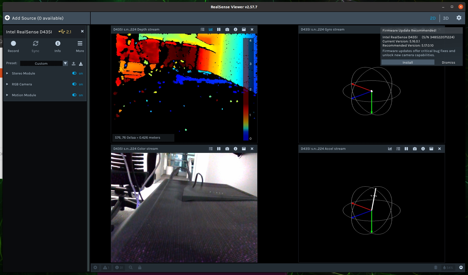
- Remember to enable 2D, Stereo Module, RGB Camera, and Motion Module on the page.
If the last mode cannot be opened, exit and reopen using
sudo realsense-viewer.
4.3.2 Start ROS Core Library Test
- Use the following command to open the camera ROS topics.
roslaunch realsense2_camera rs_camera.launch
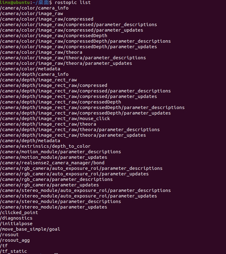
- Now check
rostopic. When the following topics appear, it indicates that the camera is running successfully.
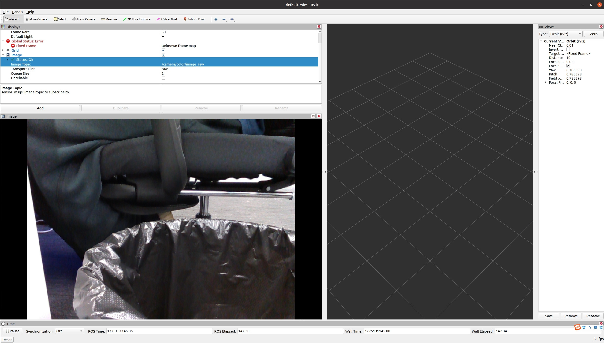
- At this point, open rviz, select the image function, and select the
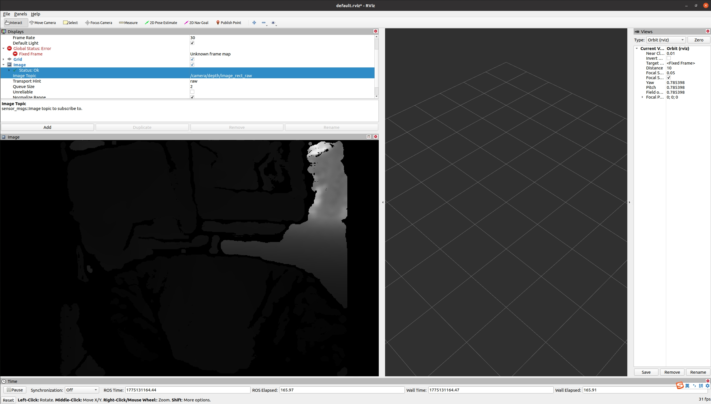
/camera/depth/image_revt_rawtopic to see the image.