Version History
| Version | Revision Date | Modified By | Change Description |
|---|---|---|---|
| v1.0 | 20260518 | damon | Initial draft of the first shipment prepared. |
| v1.1 | 20260717 | damon | Updates for Main Controller V2.1.24 Upgrade and Corrections of Previous Errors |
| v1.2 | 20260810 | damon | Information updates for the main controller V2.2.11 upgrade - Added section 6.3: Robot connection to external internet - In section 7.1 (robot body firmware upgrade), added more detailed instructions regarding the motor driver firmware - In section 5.3.3 (starting the teleoperation applet within the VR device), changed the logic of the teleoperation program's interactive interface - In section 5.4 (during teleoperation), changed the home key combination to X+A - In sections 3.2 (mode descriptions and usage flow diagrams) and 3.5 (meaning of indicator lights), added descriptions related to demo mode - In section 3.2, added a manual takeover function during inference on the actual robot - In Section 1.2 Product Specifications, the CPU of the Development Expansion Module has been changed to Intel Core Ultra. |
| v1.3 | 20260910 | yuna | Information updates for the Main Controller V2.3.22 and VR device teleoperation software V8.4.1 upgrades - In section 4.5 (remote control commands for Sole/Wheeled-Legs robots), added instructions for Wheeled-Legs auto-recharge - In sections 4.4 and 4.5 (Remote Controller Mode Switching), added the backward cycling function - Updated the operating procedure and video in section 5.3.3 (starting the teleoperation applet within the VR device) - Added section 6.4: Remote Teleoperation Configuration - Updated the online upgrade procedure and video for the VR device app in section 7.2 |
| v1.4 | 20260912 | damon | Add a section on remote controller firmware upgrade |
Safety Notice
To ensure the safety of both users and the robot, please read the following precautions carefully before use:
- Professional Use Only:This product is intended for professional use. Individuals under 18 are not advised to operate the device. The operation should only be
performed by persons with relevant technical knowledge or under the supervision of qualified personnel. - Keep Out of Reach of Children: Prevent children from approaching or interacting with the robot. In environments where children are present, take extra preca
utions and ensure the robot operates only in safe and supervised conditions. - Idle Protection: Do not leave the robot powered on and unattended. Activate mechanical or software-based suspension protection to prevent unintended movement.
- Safe Operating Environment: Keep the operating area clear of obstacles at all times. Use safety restraints or tethers when necessary toprevent accidental movement, tipping, or injury.
- Maintain a Safe Distance: Always keep the robot within your line of sight. Maintain a minimum distance of 1 meter (3 feet) from the robot during operation.
- Handling Precautions: Do not touch the robot,s joints or actuating components immediately after power-on or during transportation, as unexpected movement
may cause pinching or impact injuries. - Low Battery Warning: When a low battery warning is displayed, power off the robot and recharge the battery immediately to prevent unexpected shutdown, system malfunction, or damage.
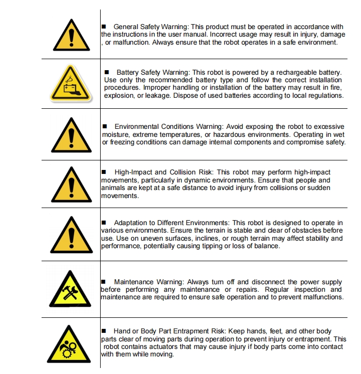
Safety Warnings
Legal and Compliance Notice
The copyright and ownership of this manual belong to Shenzhen LimX Dynamics Technology Co., Ltd. and its affiliates (collectively referred to as "LimX Dynamics"). Without written authorization from LimX Dynamics, no individual or organization may copy, scan, store, distribute, reprint, sell, transfer, modify, or otherwise use all or part of this manual for themselves or others. This manual and its contents are intended only for operating and using this product and may not be used for any other purpose.
To avoid illegal acts, possible injury, and losses, please strictly observe the following requirements:
- For safety precautions, refer to the Safety Notice. Before using this product, carefully read this document and the Safety Notice to understand your rights, responsibilities, and legal terms. Failure to comply may result in property loss or safety hazards. By using this product, you indicate that you fully understand and accept all terms in this document. Operate strictly according to the instructions and take full responsibility for your actions and any related consequences. LimX Dynamics assumes no responsibility for injury or loss caused to relevant personnel due to improper operation.
- Unauthorized disassembly, modification, or non-standard repair of the product is strictly prohibited. LimX Dynamics is not responsible for equipment faults or damage caused by such actions.
- Do not use this product in extreme environments, such as high temperature, low temperature, or corrosive chemical environments. LimX Dynamics is not responsible for equipment issues caused by such conditions.
- Under normal use conditions, issues caused by natural component wear or battery aging are not considered product quality issues, and LimX Dynamics assumes no responsibility for them.
- This product must not be used for any activity that endangers national security, including but not limited to support for terrorism, nuclear facilities, biochemical weapon development, or the design and use of weapons of mass destruction.
- Please confirm that you are not subject to any trade restrictions or sanctions; otherwise, you may not be able to use LimX Dynamics products and services normally.
- LimX Dynamics is committed to ensuring product compliance worldwide. Please comply with the laws and regulations of your region and pay attention to relevant compliance requirements.
- You must comply with the export-control laws and regulations applicable in your region.
- You must undertake to use this product for legitimate purposes and agree to accept all terms in this document.
- LimX Dynamics reserves the right of final interpretation of this agreement and may update or adjust it as needed.
1 Product Overview
1.1 Introduction
TRON 2 is a modular, composable, multi-scenario embodied-robotics research platform designed for research users. It enables users to freely implement ideas across different robot configurations. By providing open low-level interfaces and Python/C++ development compatibility, it significantly lowers the research barrier in embodied intelligence. As an ideal platform for university research and teaching as well as secondary development by industry enterprises, TRON 2 is dedicated to advancing robotics from the laboratory toward industrialization.
1.2 Product Specifications
| Parameter Category | Parameter Item | TRON 2 EDU Version | TRON 2 Standard Version | Notes |
| "–" = Not available, "o" = Optional, "✓" = Standard Version | ||||
| Mechanical Parameters | Material | Aluminum alloy, plastic | Aluminum alloy, plastic | |
| Degrees of Freedom | Single arm: 7 DOF; single leg: 5 DOF; head: 2 DOF | Single arm: 7 DOF; single leg: 5 DOF; head: 2 DOF | ||
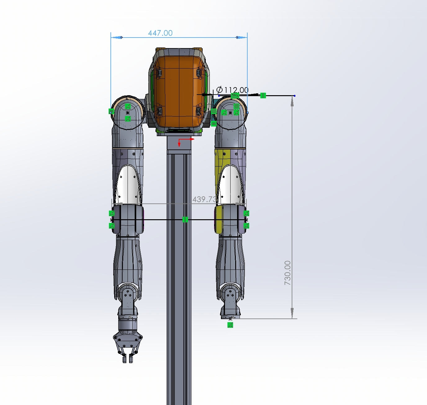
| Dimensions | Dual-Arms | - Shoulder width: 447 mm - Arm length: 730 mm (without gripper) | - Shoulder width: 447 mm - Arm length: 730 mm (without gripper) |
|
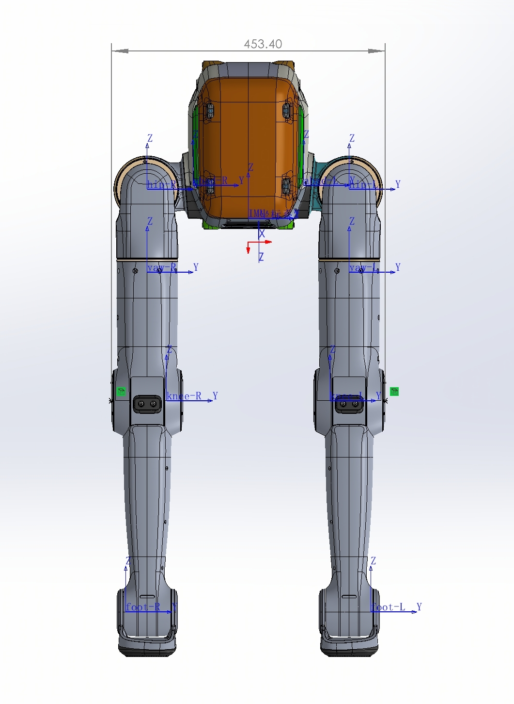
| Sole | - Overall width: 453 mm - Standing height: 987 mm | - Overall width: 453 mm - Standing height: 987 mm |
| |
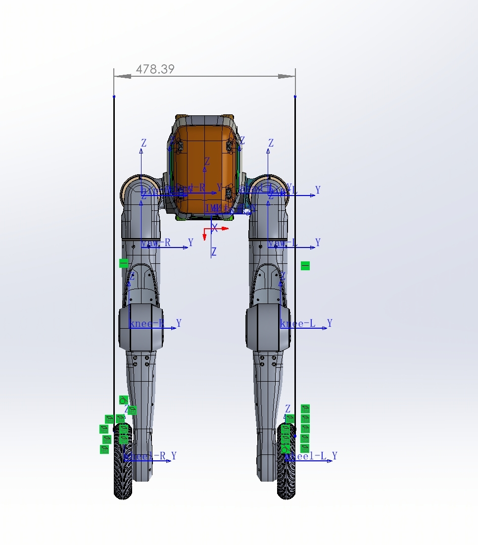
| Wheeled-legs | - Overall width: 478 mm - Standing height: 1015 mm | - Overall width: 478 mm - Standing height: 1015 mm |
| |
| Top Expansion Area | Width: 146 mm; depth: 170 mm | Width: 146 mm; depth: 170 mm | ||
| Functions | Secondary Development | √ | — | |
| Sole/Wheeled Control Functions | Four-directional Movement, Turning, Static Standing, Squatting Down In-place, Robot Height Adjustment, Stand Up After a Fall, and Ground Clearance Detection | Four-direction movement, turning, static standing, height adjustment (squat/stand), fall recovery, off-ground detection | ||
| Dual-Arm Teleoperation Method | VR device (PICO 4 Ultra) | — | ||
| Data Collection and Local Storage | √ | — | ||
| Dual-Arm Safety Boundary Protection | √ | — | ||
| Dual-Arm Configuration | Maximum End Effector Load | Maximum: 5kg per arm; Extended: 3kg per arm | Maximum: 5kg per arm; Extended: 3kg per arm | |
| Maximum End-Effector Speed | 5m/s | 5m/s | ||
| Maximum End-Effector Acceleration | 36m/s² | 36m/s² | ||
| Repeat Positioning Accuracy | ± 0.5mm | ± 0.5mm | ||
| Teleoperation Delay | 100ms | 100ms | ||
| End-Effector Type | Gripper \ Dexterous hand | Gripper \ Dexterous hand | ||
| Gripper Performance | Gripping Force: 20N Maximum; Gripping Width: 85mm | Gripping Force: 20N Maximum; Gripping Width: 85mm | ||
| Sole/Wheeled Configuration | Maximum Movement Speed | Sole: 2-3 m/s; wheeled: 3-5 m/s | Sole: 2-3 m/s; wheeled: 3-5 m/s | |
| Maximum Climbing Slope | Sole: 15°; wheeled: 30° | Sole: 15°; wheeled: 30° | ||
| Maximum Step Height | 20cm | 20cm | ||
| Maximum Load Capacity | 30kg for flat ground walking; 20kg for stair climbing | 30kg for flat ground walking; 20kg for stair climbing | ||
| Electrical Parameters | Battery Output Voltage | 46.8V | 46.8V | |
| Maximum Battery Power | 2800W | 2800W | ||
| Support for Battery Replacement | √ | √ | ||
| Battery Type | Ternary lithium battery | Ternary lithium battery | ||
| Battery Capacity | 9Ah | 9Ah | ||
| Charging Power | 542W | 542W | ||
| Charging Input Voltage/Current | 100~240V/8A | 100~240V/8A | ||
| Charging Output Voltage/Current | 54.275V/10A | 54.275V/10A | ||
| Charging Time | 20-80% Charge: 30min ; 20-100% Charge: 54min | 20-80% Charge: 30min ; 20-100% Charge: 54min | ||
| Sensor Configuration | Waist RGBD Camera | √ | √ | |
| IMU(Inertial Measurement Unit) | √ | √ | ||
| Head RGBD Camera | ✓ (only for Dual-Arms / Mobile Dual-Arms ) | — | ||
| Wrist RGBD Camera | ✓ (only for Dual-Arms / Mobile Dual-Arms) | — | ||
| Communication Interfaces | Ethernet Port | √ (1 port) | √ (1 port) | |
| USB 3.0 Port | √ (1 port) | √ (1 port) | ||
| EtherCAT Port | √ (2 port) | √ (2 port) | ||
| RS485 Port | √ (1 port) | √ (1 port) | ||
| Peripheral Charging Interfaces | 24 V Power Output Port | √ (2 port) | √ (2 port) | |
| 48 V Power Output Port | √ (1 port) | √ (1 port) | ||
| Power Supply Port | External Power Supply Port | √ (1 port) | √ (1 port) | |
| Developer Expansion Module | CPU | Intel Core Ultra | — | |
| Storage Capacity | 2TB | — | ||
| Interfaces | 3 x ETH ports, 3 x USB 3.0, 1 x 24 V input power, 1 x 12 V output power | — | ||
| Software Compatibility and Developer Tools | SDK | √ | — | |
| Robot Management Platform | √ | √ | ||
| Data Platform | √ | — | ||
| Simulation Platform | √ | — | ||
| Software Compatibility | Compatible with Python, C++ development environments; Supports ROS1/ROS2 systems | — | ||
1.3 Packing List
- Flight Case
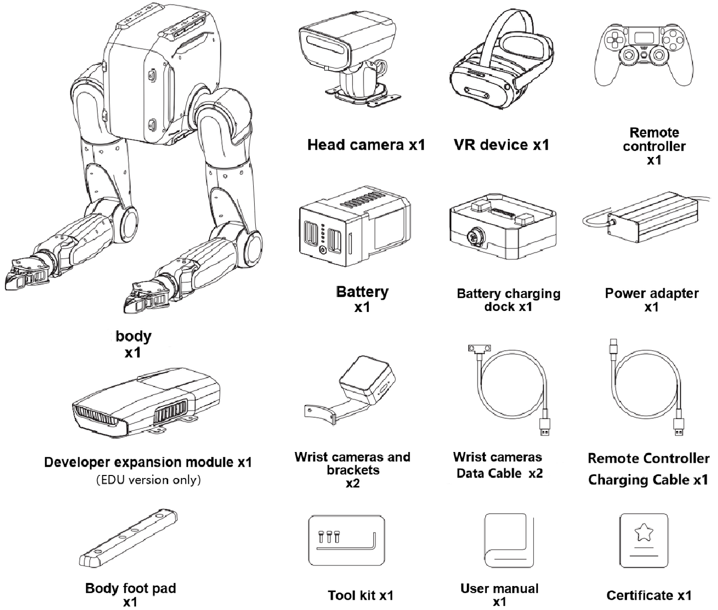
|
Carton
|
Carton
|
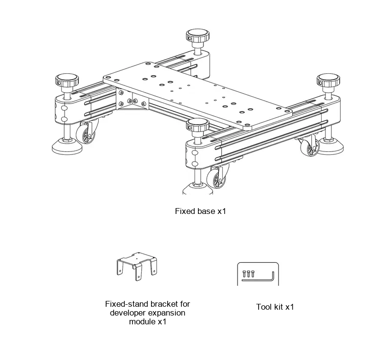
|
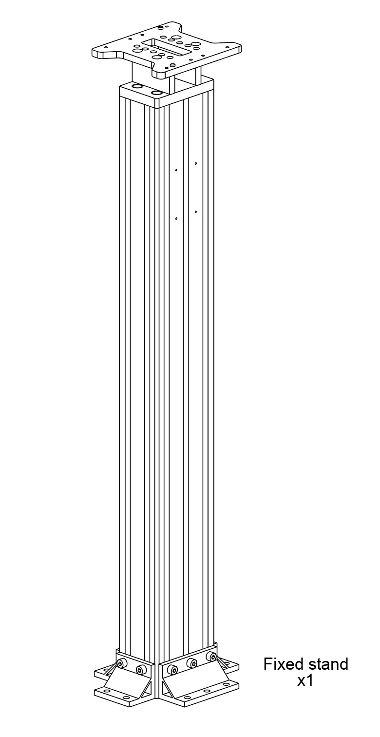
|
- Carton
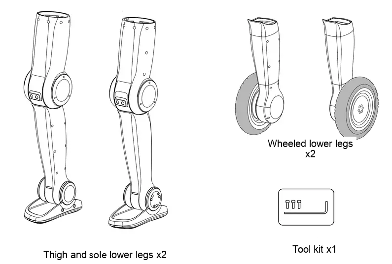
- Carton
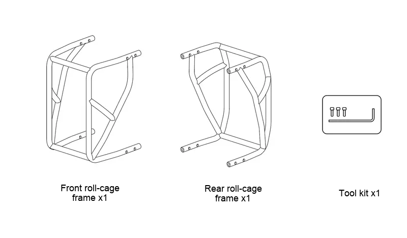
|
Wooden Crate (Equipped on mobile dual-arms version only)
|
Carton (Equipped on mobile dual-arms version only)
|
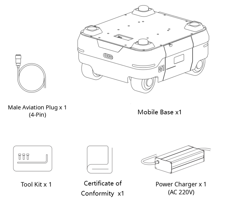
|
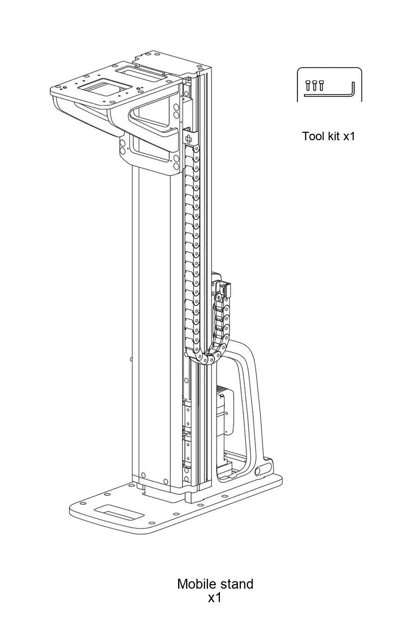
|
1.4 Body Components and Ports
Body Components
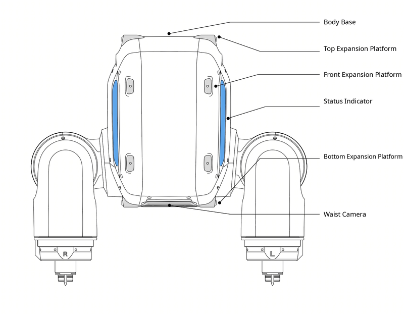
| Component/Ports | Function Description | Component/Ports | Function Description |
|---|---|---|---|
| Status Indicator | Displays overall robot status, including mode status, fault status, low-battery reminders, etc. | Peripheral Expansion Platform | Includes peripheral expansion platforms at the top, front, and bottom. All threaded holes are M4 and are used to mount external expansion devices. |
Robot Body Receptacle Interfaces
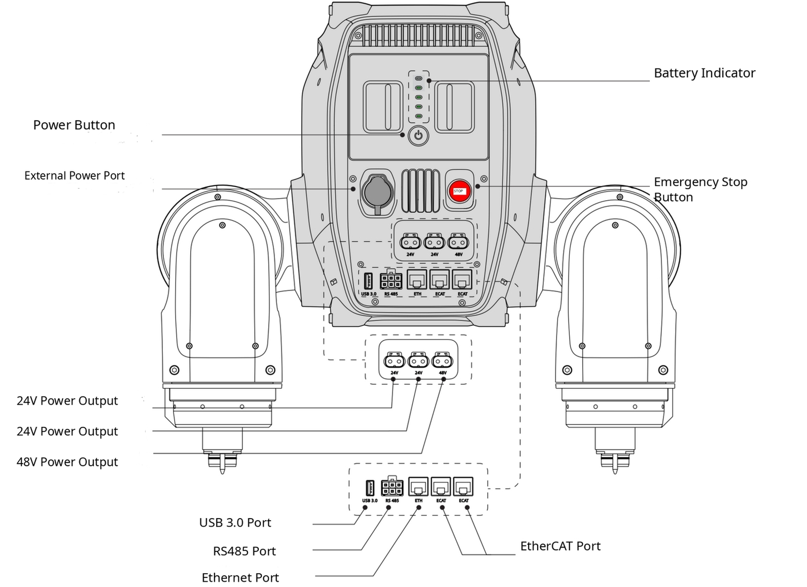
| Component/Ports | Function Description | Component/Ports | Function Description |
|---|---|---|---|
| Power Button | Used to power the robot on/off | Battery Level Indicator | Displays the current robot battery level |
| External Power Ports | Used to connect an external power adapter | Emergency Stop Button | In an emergency, press this button to enter torque-off mode, cutting motor power |
| 24 V Power Output Ports | LCB female connector, stable 24 V DC output, rated output 5 A, maximum output 20 A | 48 V Power Output Port | LCB female connector, stable 48 V DC output, rated output 10 A, maximum output 20 A |
| USB 3.0 Ports | USB-A 3.0, available for external device expansion | Ethernet Ports | Gigabit Ethernet port for connecting a computer, router, or other communication module |
| RS485 Ports | Used to expand external devices | EtherCAT Ports | Used to expand external devices |
Developer Expansion Module Ports
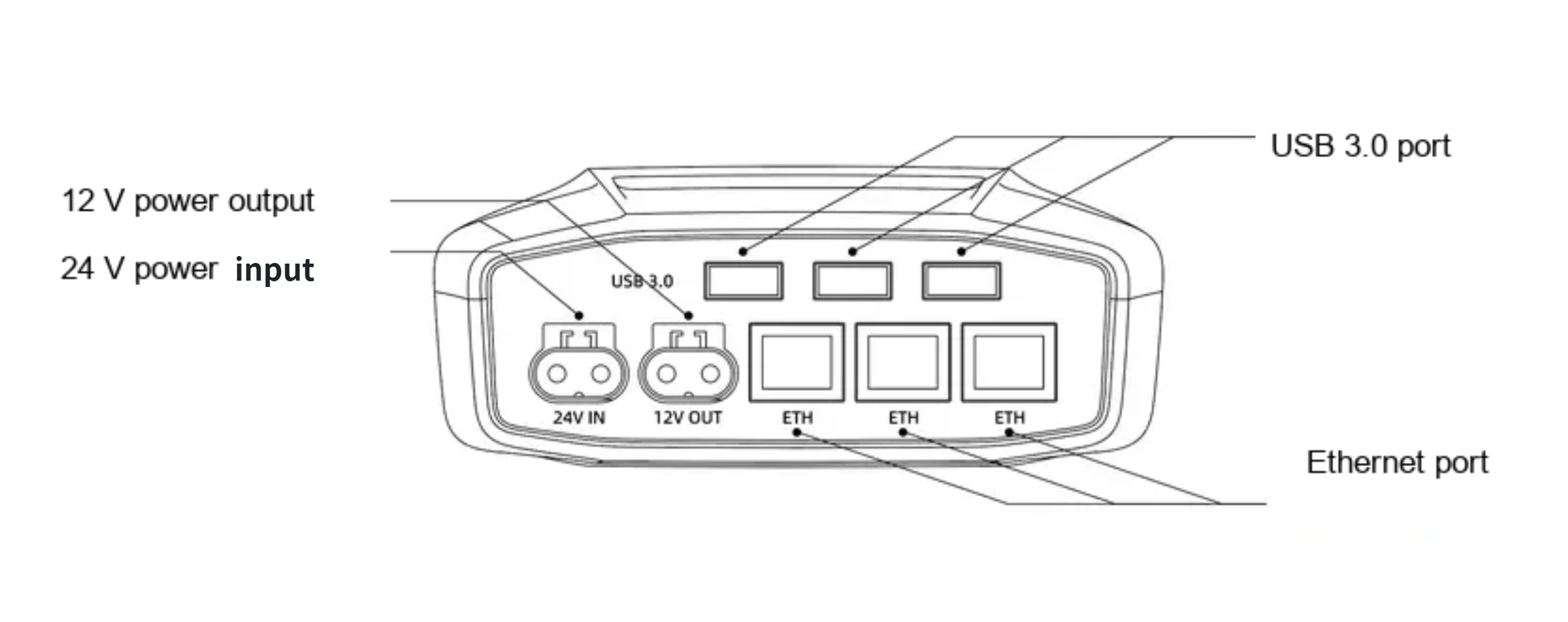
| Component/Interface | Function Description | Component/Ports | Function Description |
|---|---|---|---|
| 12 V Power Output Port | LCB female connector, stable 12 V DC output, maximum output current 5 A | Ethernet Interface | Gigabit Ethernet port |
1.5 Coordinate Frames and Joint Limits
Dual-Arms Configuration
When all joints are at zero degrees, their joint coordinate frames are shown below. Red indicates the x-axis, green indicates the y-axis, and blue indicates the z-axis.
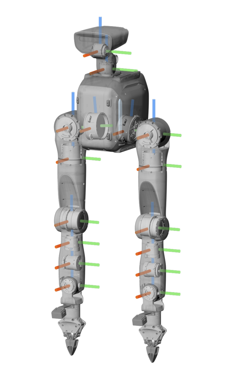
Joint numbers and limits are shown below.
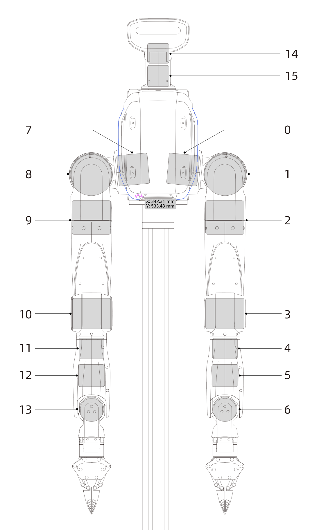
|
|
||||||||||||||||||||||||||||||||||||||||||||||||||||||||||||||||||||||||||||||||||||||||||||||||||||||||||
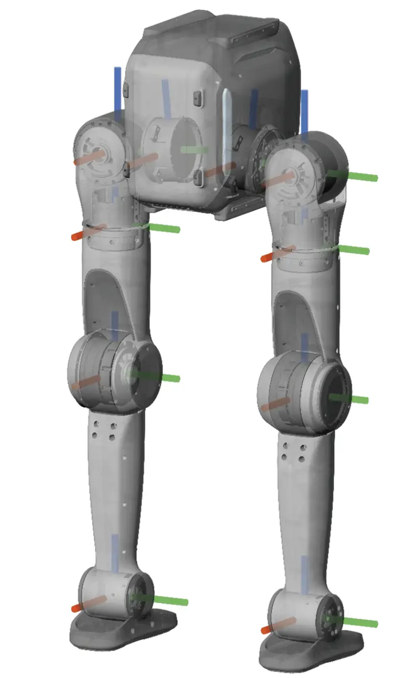
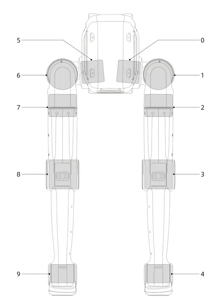
Sole/Wheeled Configuration
When all joints are at zero degrees, their joint coordinate frames are shown below. Red indicates the x-axis, green indicates the y-axis, and blue indicates the z-axis.
|
|
||||||||||||||||||||||||||||||||||||||||||||||||||||||||||||||||||||||||||||||||
1.6 Installation Guide
1.6.1 Installation Video Guide
1.6.2 Pre-Power-On Wiring Check
Never connect a 24 V power cable to a 48 V port. Connecting a power cable incorrectly may damage the robot hardware.
Mandatory Checks Before Power-On
- Verify that the robot, power adapter, and Mobile Base are all powered off.
- Check each cable label against its port label as shown in the wiring diagrams. Pay particular attention to the power cable connections.
- Verify the connector orientation. Never force a connector into a port.
- Verify that every connector is fully seated and locked, with no looseness, misalignment, or exposed metal contacts.
- Inspect the cables and connectors for damage, deformation, signs of burning, or unusual odors.
- If you cannot confirm that the wiring is correct, do not power on the robot. Contact LimX Dynamics Technical Support.
Dual-Arm Robot Wiring
Before power-on, check the Dual-Arm Robot wiring against the diagram below.
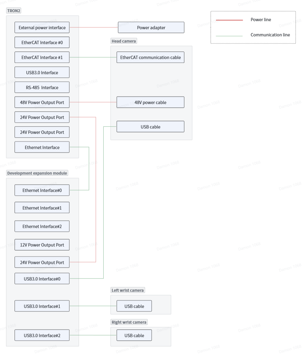
Tip
The robot can be converted from the Dual-Arm Configuration to either the Sole or Wheeled-legs Configuration. The robot-body wiring remains the same. Check the wiring against the Dual-Arm Robot wiring diagram.
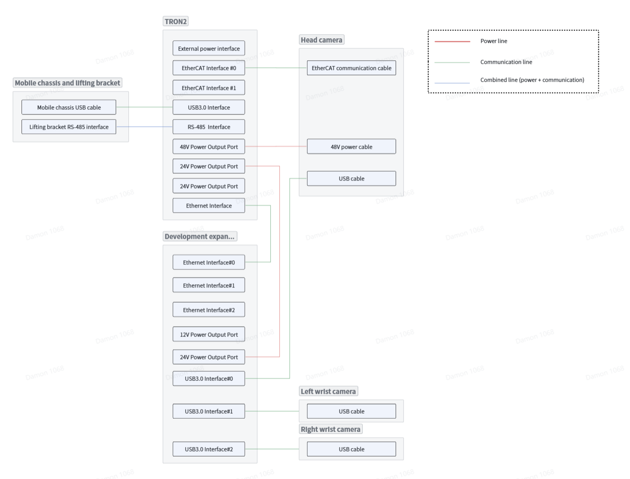
Mobile Base Wiring
This wiring diagram applies only to the Mobile Dual-Arms Robot. Before power-on, check the wiring of both the Dual-Arm Robot and the Mobile Base.
2 Battery Level Check and Charging Instructions
2.1 Robot Battery Level Check and Charging
Checking the Robot Battery Level
Short-press the power button once to check the battery level.
Charging the Robot Battery
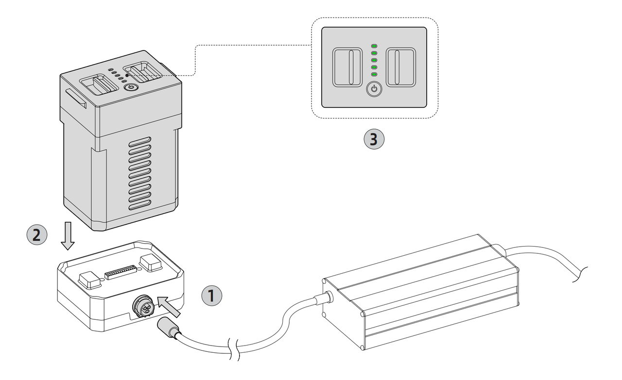
- Connect the battery charging dock and power adapter, align the aviation connector with the keyed position, and insert it.
- Insert the battery into the charging dock, press it down to ensure it is fully seated, and plug the power adapter into a power outlet (220 V AC).
- If the battery indicator flashes and the power adapter indicator is steady blue, charging has started. When the battery indicator and the power adapter indicator are both steady green, the battery is fully charged.
Battery and Adapter Indicator Lights
| Not Charging | Charging | Charging Complete | Charging Fault | |
|---|---|---|---|---|
| Battery | No light | Green flashing | Green steady | |
| Power Adapter | Green steady | Blue steady | Green steady | Red flashing |
Tip:
- If the device will not be used for an extended period, charge the battery once every three months to avoid battery damage.
- Long-term charging is not recommended. Remove the power adapter promptly after the battery is fully charged.
2.2 Remote Controller Battery Level Check and Charging
Checking the Remote Controller Battery Level
After long-pressing the Power button below the remote controller screen to turn it on, check the battery icon at the upper right of the screen.
Charging the Remote Controller
- Connect the Type-C end of the remote controller charging cable to the remote controller and connect the other end to a 5 V/1 A power supply.
- A steady green remote controller indicator means charging has started successfully.
Remote Controller Charging Indicator
| Not Charging | Charging / Charging Complete | |
|---|---|---|
| Remote Controller Indicator | No light | Green steady |
2.3 Mobile Bases Battery Level Check and Charging (Mobile Dual-Arms Version Only)
Checking the Mobile Bases Battery Level
The normal battery voltage range is 24-29.4 V. If the chassis LED flashes red, the battery voltage is too low. Charge it promptly.
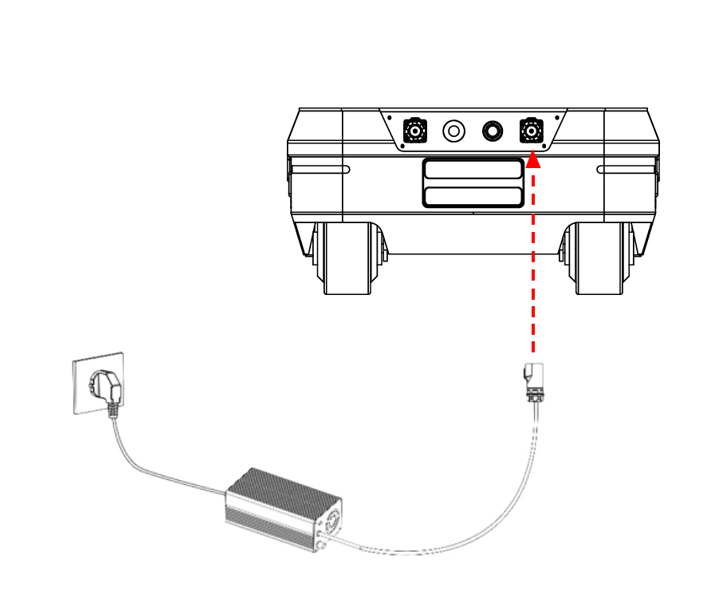
Charging the Mobile Bases
Use the 10A charger provided with the product. Insert the charger plug into the charging port on the rear of the mobile base, then connect the charger to a power source. The robot will begin charging.
3 Using Your TRON 2
3.1 Operating Environment Requirements
- Electromagnetic interference: Avoid operating near interference sources such as high-voltage power lines and mobile base stations.
- Wi-Fi signal interference: Avoid co-channel interference. If interference occurs, turn off other nearby wireless signal sources.
- Line-of-sight control: Keep the robot within visual range at all times and maintain a safety distance of at least 1 m from obstacles, crowds, water surfaces, etc.
- Temperature range: -5°C to 40°C. Outdoor use is prohibited in severe weather such as heavy fog, rain, snow, or thunderstorms.
- Water and dust protection: The robot is not waterproof or dustproof. Avoid humid, sandy, or dusty environments.
- Ground requirements: Use on flat ground with high friction. Operate cautiously if the robot must be used on smooth surfaces.
- Safety assistance: In Sole/wheeled configurations, use a tether to avoid falls during remote control and early development testing.
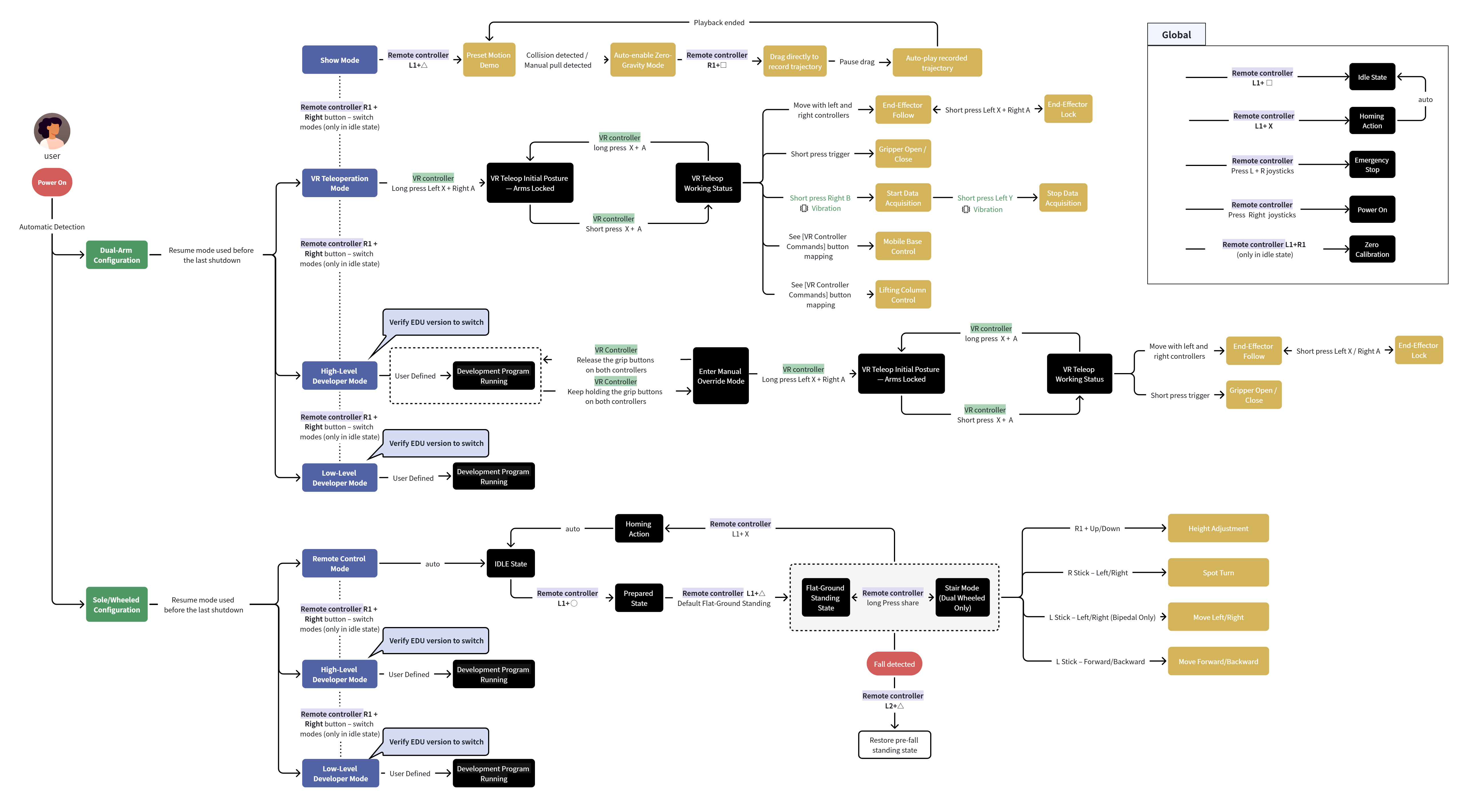
3.2 Mode Descriptions and Usage Flow
| Configuration | Mode | Mode Description |
| Dual-Arms Configuration | Show Mode | Provides Preset Motion Demo, Drag-to-Record Trajectory, and Playback of Recorded Trajectory. |
| VR Teleoperation Mode | In this mode, a VR device is used to remotely operate the robot, mainly for teleoperation, data collection, etc. | |
| High-Level Development Mode (EDU version only) | Allows calls to high-level application development interfaces to control robot motion based on built-in motion-control algorithms, such as moveJ and servoP. | |
| Low-Level Development Mode (EDU version only) | Allows calls to low-level development interfaces to directly control joints. | |
| Sole/Wheeled Configuration | Remote-Control Mode | The user controls robot motion with the remote controller, including forward/backward/left/right movement, turning, height adjustment, etc. |
| High-Level Development Mode (EDU version only) | Calls high-level application development interfaces to control robot motion based on built-in motion-control algorithms, including forward/backward/left/right movement, turning, height adjustment, etc. | |
| Low-Level Development Mode (EDU version only) | Calls low-level motion-control interfaces outside the built-in motion-control algorithms to directly control joints. |
3.3 Dual-Arms/Mobile Dual-Arms Robot Power-On/Off Procedure
Power-On Procedure
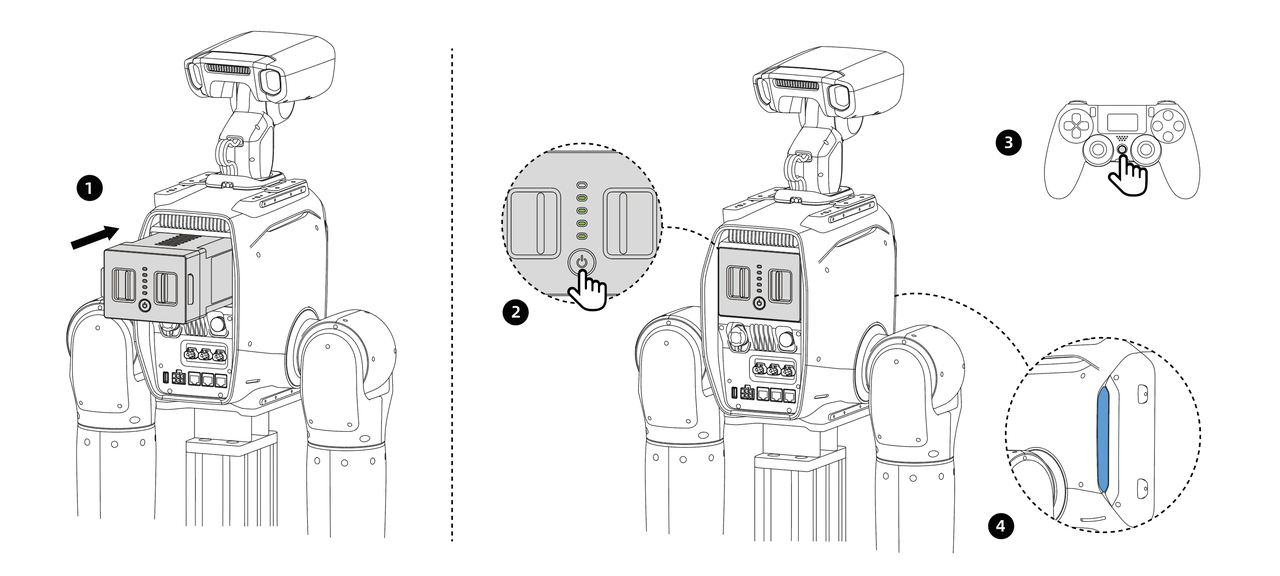
- Complete robot installation according to the installation procedure and wait for startup.
- Insert a fully charged battery into the battery compartment and press until the latch locks. For the fixed-stand version, connect the power adapter to the external power interface and to 220 V power before startup. For the mobile base version, turn on the power switch at the rear of the base.
- Short-press for 0.5 s, then long-press the robot Power button for 3 s to start the robot. The battery level indicator will turn on.
- Long-press the remote controller power button for 2 s to turn it on. The display will light up and show information.
- Observe the status indicator. During startup, it flashes white. After about 20 s, it changes to steady Blue/Cyan/Green, indicating startup is complete.
- Check the signal indicator on the remote controller display. If a signal is shown, pairing has succeeded and startup is complete.
Tip:
The robot can start normally only after the head is installed and the head joint power cable and joint communication cable are connected.
Power-Off Procedure
- To stop robot motion, press
L1+Xsimultaneously in remote-control mode to enter idle state. All joint motors enter torque-damping state and will slowly move downward. - For the fixed-base version, unplug the external power interface. For the mobile base version, turn off the power switch at the rear of the base.
- Short-press for 0.5 s, then long-press the robot Power button for 3 s to power off. The battery level indicator and status light will turn off.
- Long-press the remote controller power-off button for 3 s to power off. The display will turn off.
Tip:
Note: Enter idle state first and allow the joint motors to return slowly. If the power-off button is pressed directly, the joints will drop immediately and may damage the robot.
3.4 Sole/Wheeled Robot Power-On/Off Procedure
Power-On Procedure
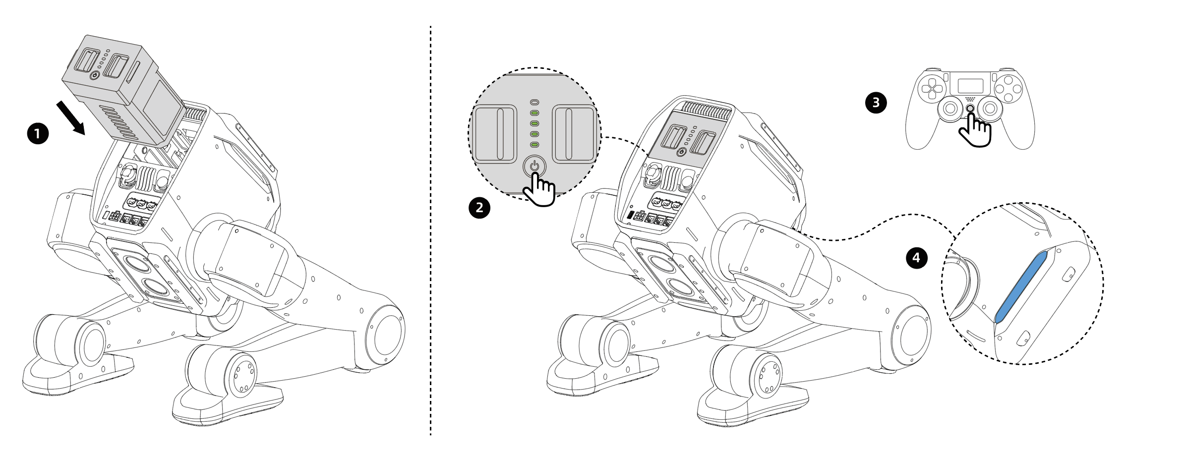
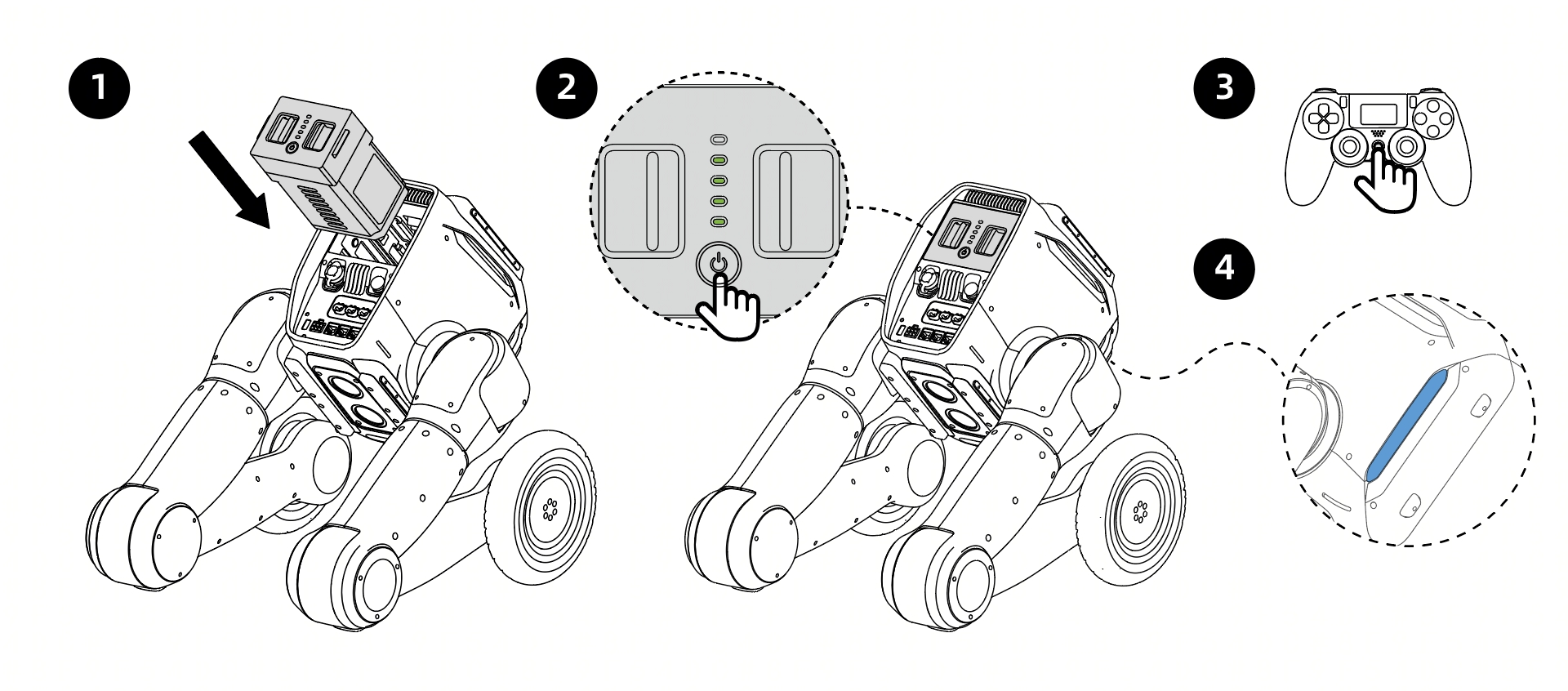
- Before powering on, place the robot in the position shown and keep it self-balanced.
- Insert a fully charged battery into the battery compartment and press until the latch locks.
- Short-press for 0.5 s, then long-press the robot Power button for 3 s to start the robot. The battery level indicator will turn on.
- Long-press the remote controller power button for 2 s to turn it on. The display will light up and show information.
- Observe the status indicator. It flashes white during startup, and steady blue indicates startup is complete.
- About 20 s after startup, the body status indicator changes from white to steady Blue/Cyan/Green. Check the signal indicator on the remote controller display. If a signal is shown, pairing has succeeded and startup is complete.
Power-Off Procedure
- To stop robot motion, press
L1+Xsimultaneously in remote-control mode to enter squat state and let the device land stably. - Long-press the robot power-off button for 3 s to power off. The battery level indicator and status light will turn off.
- Long-press the remote controller power-off button for 2 s to power off. The display will turn off.
- After all indicators turn off, remove the battery.
3.5 Robot Light Indicator Meanings
| Event/Status | Indicator Color | Indicator Description | Frequency (seconds/time) |
|---|---|---|---|
| TRON2 Robot Body | |||
| Starting Up | White slow flashing | Startup self-test in progress | 1 |
| Fault Warning | Red steady | Robot fault detected | / |
| Low Battery Warning | Red flashing | Robot battery low (below 20%) | 2 |
| Critically Low Battery Warning | Red fast flashing | Robot battery low (below 5%) | 0.5 |
| Emergency Stop State | Yellow flashing | Body emergency stop button triggered | 2 |
| Show Mode | Blue-Violet | After startup or mode switching, the current mode status will be shown. | / |
| Remote-Control Mode (for Sole/wheeled) | Steady blue | After startup or mode switching, the current mode status will be shown. | / |
| VR Teleoperation Mode (for dual-arms configuration) | Steady blue | After startup or mode switching, the current mode status will be shown. | / |
| High-Level Developer Mode | Steady cyan | After startup or mode switching, the current mode status will be shown. | / |
| Low-Level Developer Mode | Steady green | After startup or mode switching, the current mode status will be shown. | / |
| Stair Mode (only for wheeled) | Purple dynamic | Robot is in stair mode | 2 |
| Fall (for Sole/wheeled) | Steady yellow | Robot fall detected | / |
| Off-Ground Detection (for Sole/wheeled) | Yellow breathing | Robot is in off-ground detection state | 2 |
| Mobile Chassis (mobile dual-arm version only) | |||
| Error | Red steady | Error occurred | / |
| Low Battery Warning | Red flashing | Battery level below 15% warning | 1 |
| Charging | Green slow flashing | Charging current greater than 1 A | 2 |
| Parking | Yellow steady | Four wheels locked in an X configuration | / |
| Normal Motion Mode | Blue steady | Standby state or straight-line motion | / |
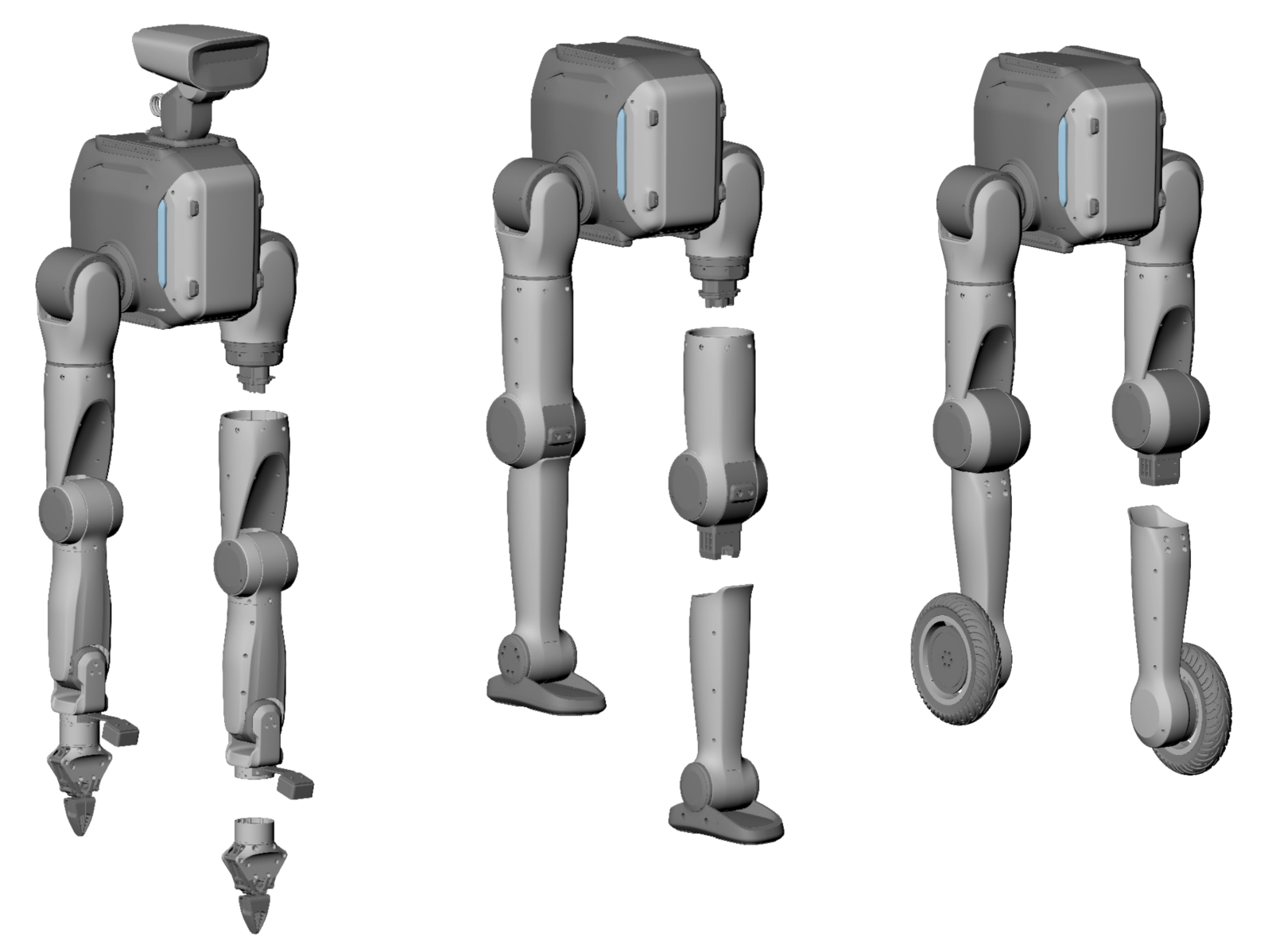
3.6 Robot Configuration Switching
- Automatic recognition is supported between configurations; manual configuration is not required.
- The leg and arm configurations share the same first three joints. To replace an arm or leg, detach it below the hip (for legs) or shoulder (for arms) joint. This can be done by one person using the supplied toolkit.
- Switching between bipedal and wheeled-biped configurations can be completed quickly. The mounting structure includes poka-yoke design to prevent the feet from being installed front/back reversed or the wheeled legs from being installed inside/out reversed.
4 Remote Controller Instructions
4.1 Remote Controller Power On/Off
- Turn on the remote controller: Press and hold the Power button for more than 2 s. When you hear a beep, the remote controller has turned on successfully and enters the default interface.
- Turn off the remote controller: Press and hold the Power button for more than 2 s. When you hear a beep, the remote controller turns off and the display goes dark.
4.2 Screen Information
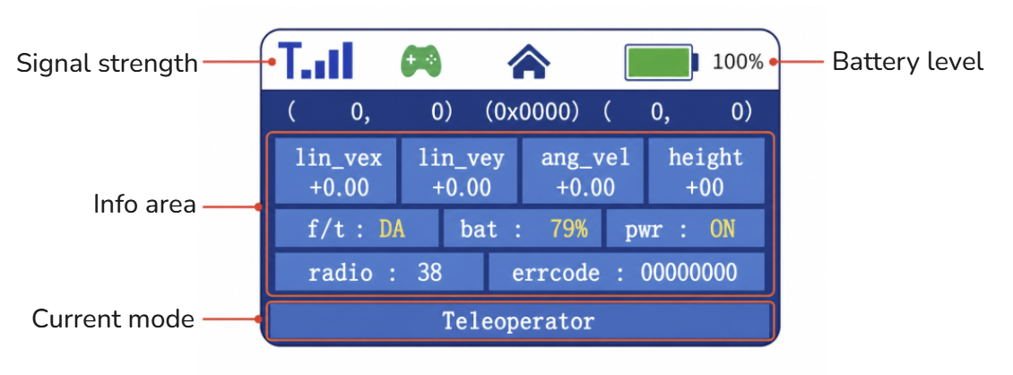
Signal Strength: When the remote controller is not connected to the robot, no signal icon is shown. After connection, blue signal bars are displayed. More lit bars indicate stronger signal.
Battery Level: Indicates the remote controller battery level
Information Area: Returns the robot's current mode, battery level, whether the robot is powered on, etc.
Current Mode/Status: High-Level Development(High-Level Developer Mode)/Low-Level Development(Low-Level Developer Mode)/Teleoperator(Remote-Control Mode)/show Mode/Idle(idle state in different modes)
4.3 Remote Controller Buttons
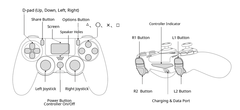
4.4 Dual-Arms/Mobile Dual-Arms Robot Remote-Control Commands
| Concept | Command Description | Prerequisite | Button | Notes |
| Mode Switching | Cycles through modes in the dual-arm configuration |
Idle state | R1 + Right: Cycle forward through the modesR1 + Left: Cycle backward through the modes |
After startup, the robot remains in the mode used before shutdown by default |
| Return Action | - In dual-arms mode, the homing action consists of the arms swinging outward and then hanging down naturally (if the safety protection function is enabled, this triggers the arm's table-avoidance action). - After completing the homing action, the robot automatically enters the idle state (the joint motors are in torque damping mode). |
Effective only in Remote-Control Mode and High-Level Developer Mode |
L1+X |
|
| Enters the idle state directly | Does not execute the return action. All joint motors enter torque-damping state and slowly move downward. |
Global | L1+ □ |
Use only in emergencies when the return action fails |
| Emergency Stop Button | All motor drives are immediately powered off, but battery power and indicator lights remain on. The whole robot will drop. |
Global | Press the left joystick + right joystick |
Triggering emergency stop in any mode or state immediately cuts power to all motors |
| Emergency Stop Release | Motors power on again | Emergency Stop State | Press the Right joystick button |
Single-clicking has no effect in other states. After release, the robot enters damping state. |
| Zero Calibration | Used to recalibrate joint zero positions | Idle state | L1+R1 |
Zero calibration is required only after the main controller has been upgraded or after severe impact causes zero-position loss or position drift. |
4.5 Sole/Wheeled Robot Remote-Control Commands
| Command | Command Description | Prerequisite | Button | Notes |
| Mode Switching | Cycles through modes in the two-leg configuration | Idle state | R1 + Right: Cycle forward through the modesR1 + Left: Cycle backward through the modes |
After startup, the robot remains in the mode used before shutdown by default |
| Enter Prepared State | Performs ground-contact/head-lift action | Idle state | L1+ ○ |
|
| Enters the idle state directly | Does not execute the return action. All joint motors enter torque-damping state and slowly move downward. |
Global | L1+ □ |
Use only in emergencies when the return action fails |
| Stand Up in Place | The robot stands up from ready state | Ready state | L1+ △ |
|
| Return Action | - In the sole/wheeled configuration, the return action is squat-and-fold. - After the return action is complete, the robot automatically enters idle state (joint motors are in torque-damping state). |
Effective only in Remote-Control Mode and High-Level Developer Mode | L1+X |
|
| Forward/Backward Movement | The robot moves forward/backward according to remote-control commands | Standing state | Left joystick up/down |
|
| Left/Right Movement (sole only) |
The robot moves left/right according to remote-control commands | Standing state | Left joystick left/right |
|
| Turn in Place | The robot rotates clockwise/counterclockwise according to remote-control commands | Standing state | Right joystick left/right |
|
| Height Adjustment | The user can adjust body height within the allowed range using the remote controller | Standing state | Hold R1 + Up/Down buttons.The robot descends/ascends at constant speed and stops when released. |
After power cycling, the robot returns to the default position and does not remember the previous height setting |
| Flat-Ground/Stair Mode Switching (wheeled-biped only) |
Switches between stair mode and flat-ground mode | Standing state | Press the Share button for 2 s |
|
| Fall Recovery | Restores the robot to standing after an accidental fall | Fall detected | L2+ △ |
This key combination has no effect when the robot is in normal state |
| Emergency Stop Button | All motor drives are immediately powered off, but battery power and indicator lights remain on. The whole robot will drop. |
Global | Press the left joystick + right joystick |
Triggering emergency stop in any mode or state immediately cuts power to all motors |
| Emergency Stop Release | Motors power on again | Emergency Stop State | Press the Right joystick button |
Single-clicking has no effect in other states. After release, the robot enters damping state. |
| Zero Calibration | Used to recalibrate joint zero positions | Idle state | L1+R1 |
Zero calibration is required only after the main controller has been upgraded or after severe impact causes zero-position loss or position drift. |
The TRON 2 Wheeled-Legs Configuration supports auto-recharge. For usage instructions, see the TRON 2 Auto-Recharge Base User Manual in the Documentation Center.
Tip:
After emergency stop is triggered, power to all motors is immediately cut off (confirm the emergency stop state before startup).
a.Body emergency stop: The robot is in emergency stop state when the emergency stop button is pressed, and not in emergency stop state when it is released. After emergency stop is released, the robot must be powered on again to restore its state.
b.Remote controller emergency stop: Pressing theleft and right joystickssimultaneously enters emergency stop state. Press theright joystick buttonto exit emergency stop state, and the robot state will automatically recover after a few seconds.
5 VR Device and Dual-Arms Teleoperation Instructions
5.1 VR controller Buttons
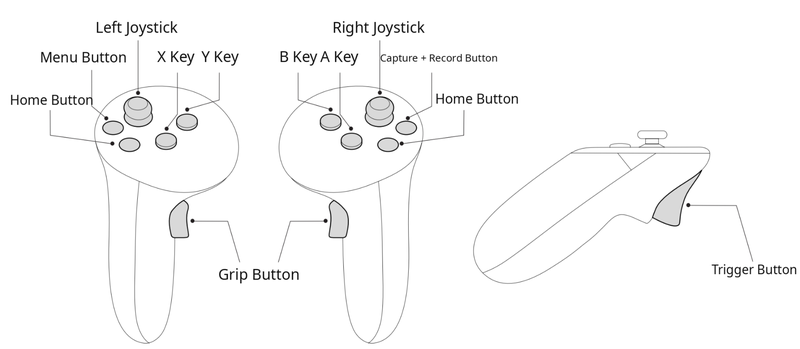
5.2 VR controller Commands
| Dual-Arms | |||
|---|---|---|---|
| Concept | Command Description | Prerequisite | Button |
| Start VR Teleoperation | Enters the initial zero position for VR teleoperation from the idle-state posture; the grippers also perform zero calibration. | Robot is in VR Teleoperation Mode | Long-press (>1 s) the X button on the left controller and the A button on the right controller simultaneously |
| Return to Initial Teleoperation Zero Position |
During teleoperation, use the VR controllers to return the arms to the initial zero position (elbows folded forward 90°). | VR teleoperation working state | Long-press (>1 s) the X button on the left controller and the A button on the right controller simultaneously |
| End-Effector Following | Hold the VR controllers; the robotic arm tips follow. | VR teleoperation initial zero state / VR teleoperation working state |
None |
| End-Effector Lock | During VR teleoperation, an arm can be paused; a typical use is holding the other arm fixed for one-handed operation. - In the zero-return locked state, simultaneously click the X button on the left controller and the A button on the right controller- During teleoperation, click the X button on the left controller to pause the left arm; click again to resume- During teleoperation, click the A button on the right controller to pause the right arm; click again to resume |
VR teleoperation initial zero state / VR teleoperation working state |
Short-press the X button on the left controllerShort-press the A button on the right controller |
| Gripper Control | Remotely closes and opens the grippers; one short press closes/opens the gripper. | VR teleoperation initial zero state / VR teleoperation working state |
Left/right Trigger Button |
| Start Data Collection | Starts collecting teleoperation data When the VR device receives the data-collection start signal from the robot, the VR controllers vibrate for feedback and the Data Collection platform status updates synchronously. |
VR teleoperation working state | B button on the right controller |
| Stop Data Collection | Stops collecting teleoperation data When the VR device receives the data-collection stop signal from the robot, the VR controllers vibrate for feedback and the Data Collection platform status updates synchronously. |
VR teleoperation working state | Y button on the left controller |
| Mobile Base | |||
| Concept | State Description | Prerequisite | Button |
| Chassis Mode Selection | Selects Ackermann Mode or Diagonal Movement Mode for the chassis | VR teleoperation working state | The default out-of-box mode is Ackermann Mode Long-press the right joystick for 1 s to switch to Diagonal Movement ModeLong-press the left joystick for 1 s to switch to Ackermann Mode |
| Forward Movement | Robot moves forward | VR teleoperation working state | Push the left joystick forward |
| Backward Movement | Robot moves backward | VR teleoperation working state | Push the left joystick backward |
| Ackermann Rotation | In Ackermann Mode, the drive wheels rotate to turn the chassis | VR teleoperation working state | In Ackermann Mode, push the right joystick left/right |
| Diagonal Movement | In Diagonal Movement Mode, the chassis does not rotate; the drive wheels turn and the chassis moves diagonally left/right | VR teleoperation working state | In Diagonal Movement Mode, push the right joystick left/right |
| Speed Adjustment | The Mobile Base speed can be adjusted with the joystick | VR teleoperation working state | The farther the left joystick is pushed forward/backward, the higher the speed. Stroke 0 means speed 0; maximum stroke means maximum speed. |
| Parking State | When the robot needs to remain stopped at a fixed position for a long time (such as parking or performing fixed-table tasks), switch the chassis to Parking State. The four wheels lock in an X-shaped four-wheel steering configuration. | VR teleoperation working state | Long-press the Grip Button on the left controller and the right joystick simultaneously for 1 s |
| Emergency Stop | For the TRON 2 dual-arm configuration with a Mobile Base, the Mobile Base also stops immediately when emergency stop is triggered. | VR teleoperation working state | VR controllers Press the VR left and right joysticks simultaneouslyRemote Controller Press the left and right joysticks simultaneously |
| Lift Stand | |||
| Concept | State Description | Prerequisite | Button |
| Raise | Controls the stand to raise the robot height | VR teleoperation working state | Hold the Grip Button on the right controller and push the left joystick forward |
| Lower | Controls the stand to lower the robot height | VR teleoperation working state | Hold the Grip Button on the right controller and push the left joystick backward |
| Return to Zero | Sends a command to return the stand to the zero position (the zero position is the top end of the stand, making battery removal easier). | VR teleoperation working state | Long-press the Grip Button on the right controller and the left controller joystick simultaneously for 1 s |
5.3 Teleoperation Preparation
5.3.1 Dual-Arms Zero Calibration
Tip:
- Zero calibration is required only after the main controller has been upgraded or after severe impact causes zero-position loss or position drift.
- In the mobile chassis configuration, raise the robot to the highest point before performing zero calibration.
- After zero calibration is complete, wait about 5 seconds while the robot refreshes the new zero-position information before performing other operations.
- Press
L1+Xto ensure the dual arms are in idle state and hanging naturally; - Press
L1+R1on the remote controller to start automatic zero calibration. After calibration ends, the dual arms should hang naturally; - If the indicator turns red during the process, zero calibration has failed. Try calibrating again.
5.3.2 Switching the TRON2 Robot to Teleoperation Mode
Press R1+Right button on the remote controller to switch to Teleoperation Mode.
5.3.3 Starting the Teleoperation App on the VR Device
Note: Do not remove the protective sticker covering the detection sensor before teleoperation use (otherwise the headset may frequently enter sleep mode).
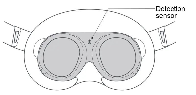
- When connecting the VR device to the robot for the first time, wear the VR Headset and complete the following settings in the VR interface.
- Tip: Point with the right-hand controller. Short-press the Trigger Button on the right-hand controller to select or confirm.
| Step | Operation | Illustration |
|---|---|---|
| 1. Power on the VR device | Press and hold the Power Button on the right side of the Headset for approximately 3 seconds to power on, then put on the Headset to enter the system home screen | 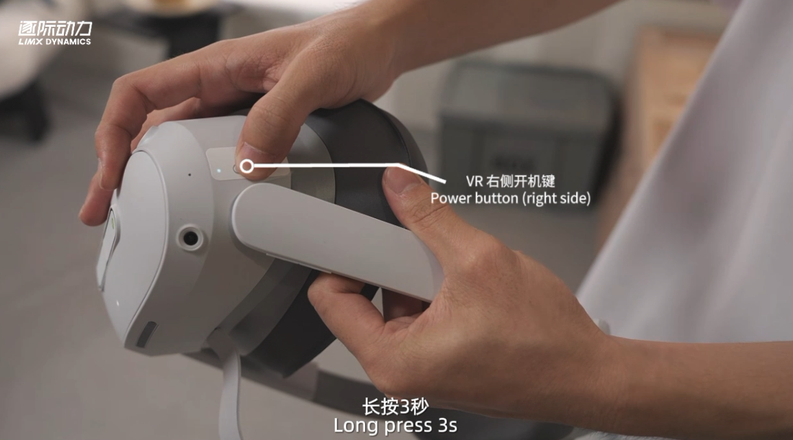 |
| 2. Connect to the robot Wi-Fi | In the quick panel / Settings, connect to TRON2A_XXX_2.4G or TRON2A_XXX_5G with password 12345678 |
|
| 3. Start the teleoperation app | Library > Unknown Sources > Limx_teleop |
|
| 4. Configure and connect | Select tron2-offline, enter 10.192.1.2 as the IP, and click Connect |
- Click Connect to enter the TRON 2 teleoperation working state. The default see-through view displays the head camera and the left and right wrist camera feeds. The wrist camera feeds can be toggled on or off in the lower-right corner.
Note: If prompted whether to enable body following during the process, select No.
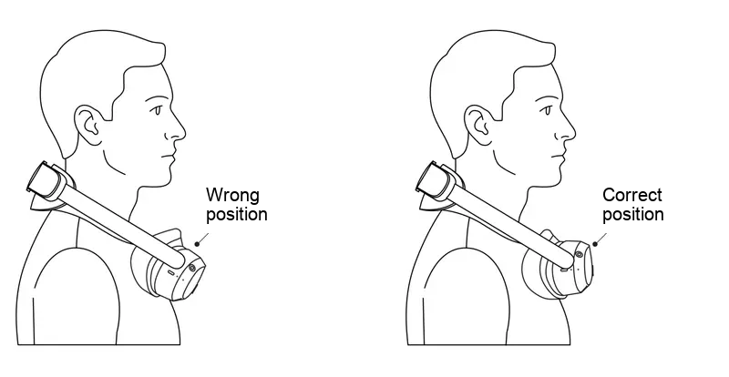
- Hang the VR headset horizontally around your neck, as shown below. Hold the VR controllers in your hands, ready for teleoperation.
5.4 Using Teleoperation
5.4.1 Dual-Arms Zero Return: Entering the Ready Posture
Long-press the left X button + right A button simultaneously for at least 1.0 s. After zero return is complete, the dual arms enter the teleoperation ready state, with the forearms extended forward at 90° to the upper arms. This operation can also be performed during teleoperation to return the dual arms to the ready state.
Right after startup, entering the teleoperation ready state requires long-pressing the
left X button + right A buttonsimultaneously for about 3.0 s.
5.4.2 Entering Teleoperation Working State
Dual-arm motion unlock: Hold the controllers with both hands, keep your arms close to the robot arms' posture, and hold the controllers level and pointing forward. Simultaneously short-press X+A for about 0.2 s to unlock the dual arms. The arm tips then start following the controllers, and the robot enters the teleoperation working state.
⚠️ When operating for the first time, use small, slow movements. Avoid sudden large movements of the controllers, which can cause the robotic arms to swing rapidly or strike nearby objects. The teleoperation link introduces a latency of about 100 ms; allow a lead time for your movements.
5.4.3 Gripper Grasping
Press the left trigger button/right trigger button to open the left/right gripper; press again to close it.
5.4.4 Mobile Base and Lift Stand Control
At this point, the Mobile Base and Lift Stand can be controlled normally according to the VR controller commands.
6 Robot Network Connection
6.1 PC to dual-arm – Wired
- Use an Ethernet cable to connect the Gigabit Ethernet port on the robot's rear side to the PC Ethernet port.
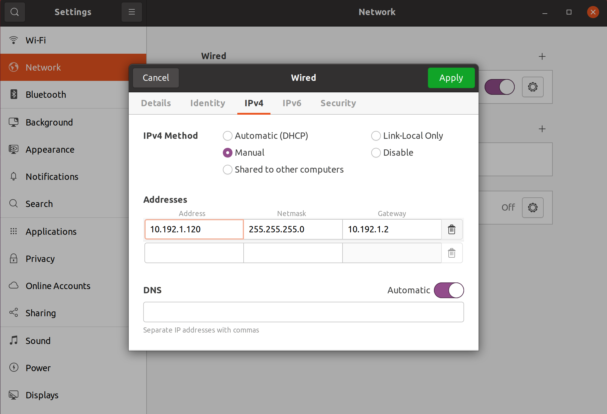
- Modify the IP address of the personal computer to the same network segment as the robot to access the system. The robot IP address is 10.192.1.2. For example, set the PC address to 10.192.1.120.
6.2 PC to dual-arm – Wireless
- After the robot startup is complete, use a personal computer to connect to the robot Wi-Fi. The name format is usually "TRON2A_XXX_2.4G" or "TRON2A_XXX_5G".
- Enter the Wi-Fi password:
12345678.
6.3 dual-arm to an External Network
- After the PC is connected to the dual-arm, open a browser and access the dual-arm management page at
http://10.192.1.2:8080. - Click the Wi-Fi icon on the right, and enter the Wi-Fi information required for the dual-arm to connect, including Wi-Fi Band, Wi-Fi SSID, Wi-Fi Password, and Router Admin Password.
6.4 Remote Teleoperation Configuration
After completing the following settings, you can use a VR device to teleoperate a bound robot over an external network.
Before proceeding, complete the settings in 6.3 dual-arm to an External Network, and make sure both the robot and the VR device are connected to an external network.
6.4.1 Binding the Robot
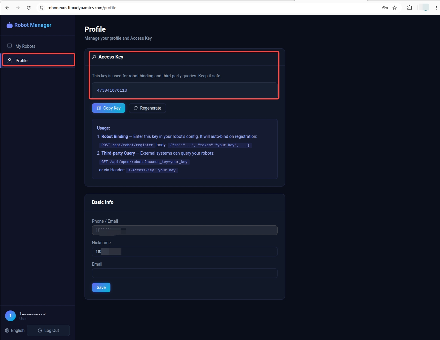
1.Access the Robot Management Platform at http://robonexus.limxdynamics.com/ over the external network. Register and log in to your account, then obtain the Access Key on the personal information page.
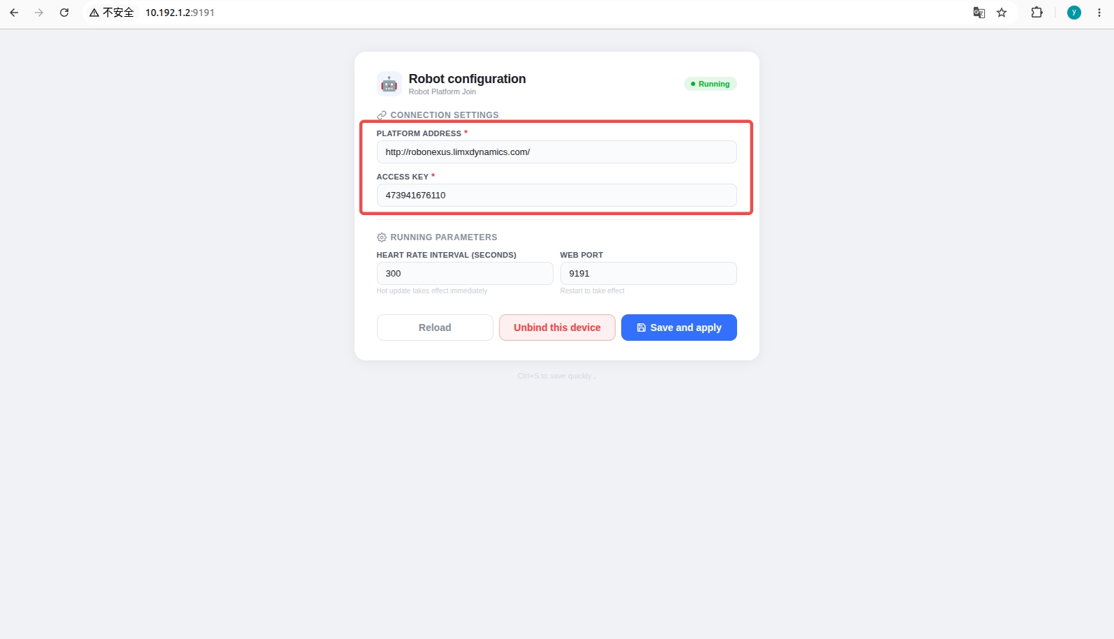
2.Connect to the robot via Wi-Fi or the Ethernet port, then access the Remote Teleoperation Configuration page at http://10.192.1.2:9191 in a browser. Enter the platform address http://robonexus.limxdynamics.com/ and your account's Access Key, then save and apply the configuration.
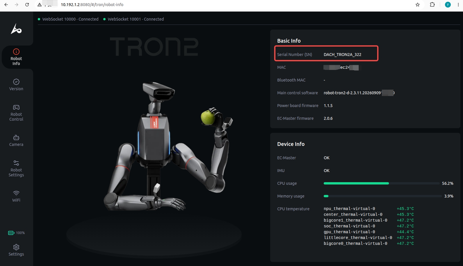
 3.Access the robot management page at http://10.192.1.2:8080, and record the robot's Serial Number (SN) under "Robot Information".
6.4.2 Connecting the VR Device
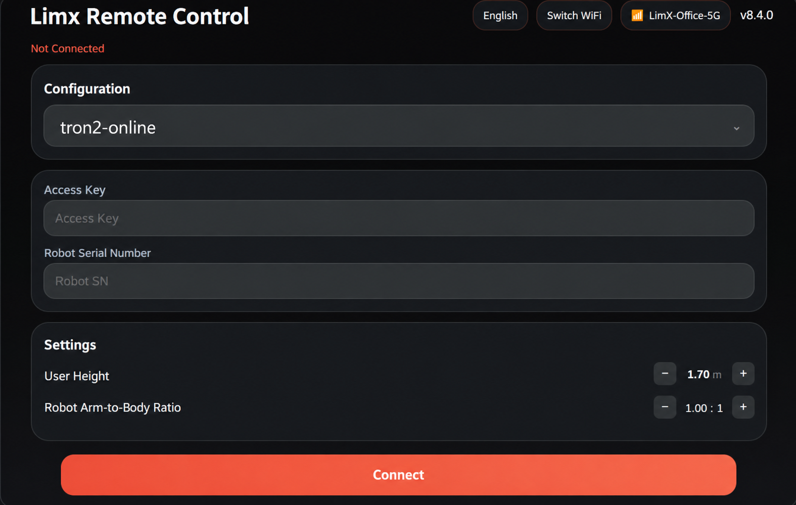
- Open the teleoperation app on the VR device and select connection via an external network.
- Select
tron2-onlineas the configuration, enter your account's Access Key and the robot's serial number, then click "Connect".
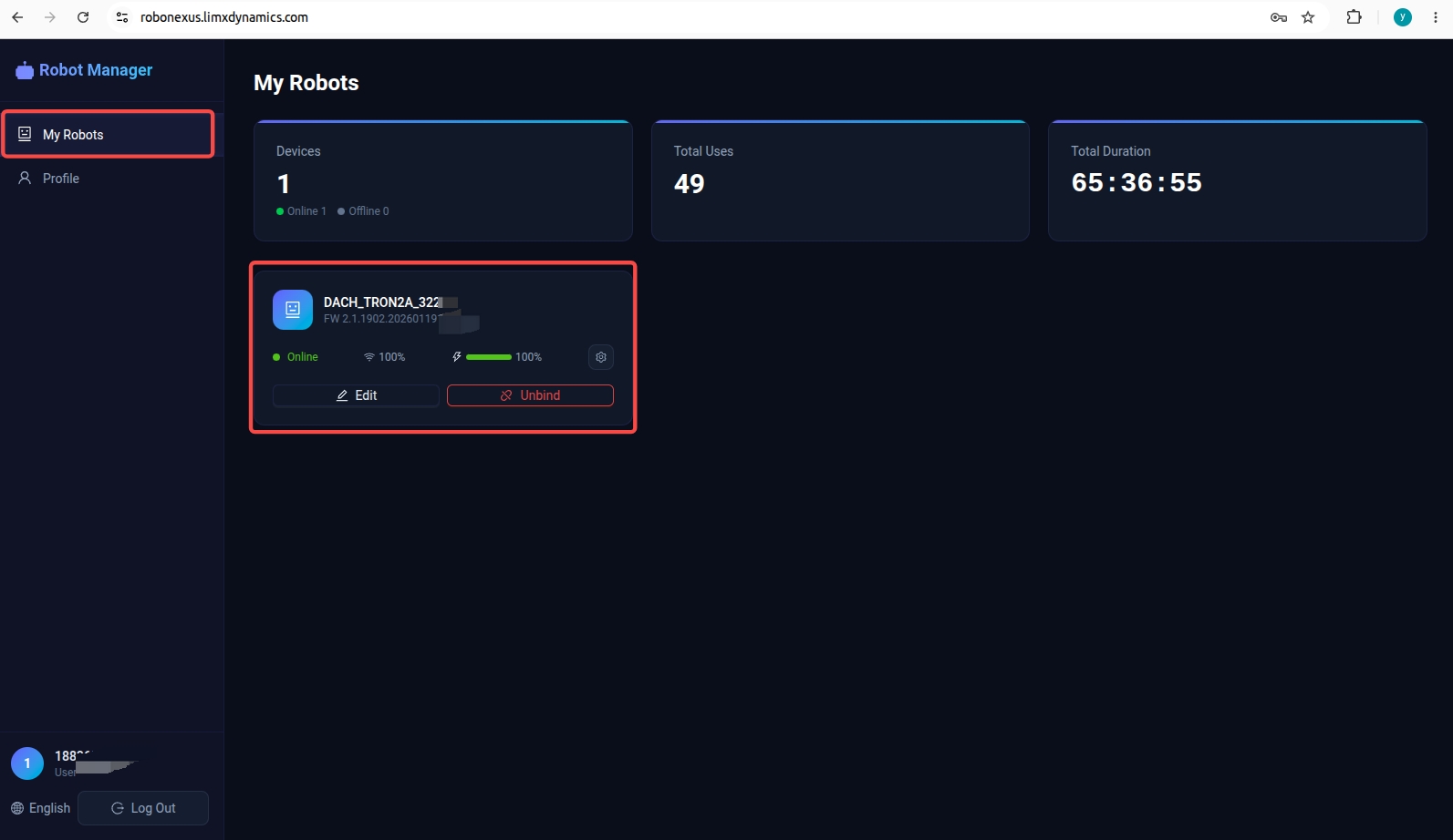
 3.After the connection succeeds, the Robot Management Platform displays the robots currently available for remote teleoperation.
7 Robot Software Upgrade
7.1 Robot Body Firmware Upgrade
Use a browser to enter the robot management page and select the robot software version downloaded locally in advance for upgrade. The steps are as follows:
- Connection and IP settings:
a. Connect a personal computer to the robot.
b. Use the Shell commandping 10.192.1.2to ensure the connection is normal. - Access the management page: enter the following in the browser address bar:http://10.192.1.2:8080 to enter the robot management page.
- Select and upgrade software:
a. Go to the LimX Dynamics official website → Downloads ,at https://www.limxdynamics.com/en/downloads. Select the product model TRON2, choose the firmware type and version you need, and download the firmware package to your local computer.
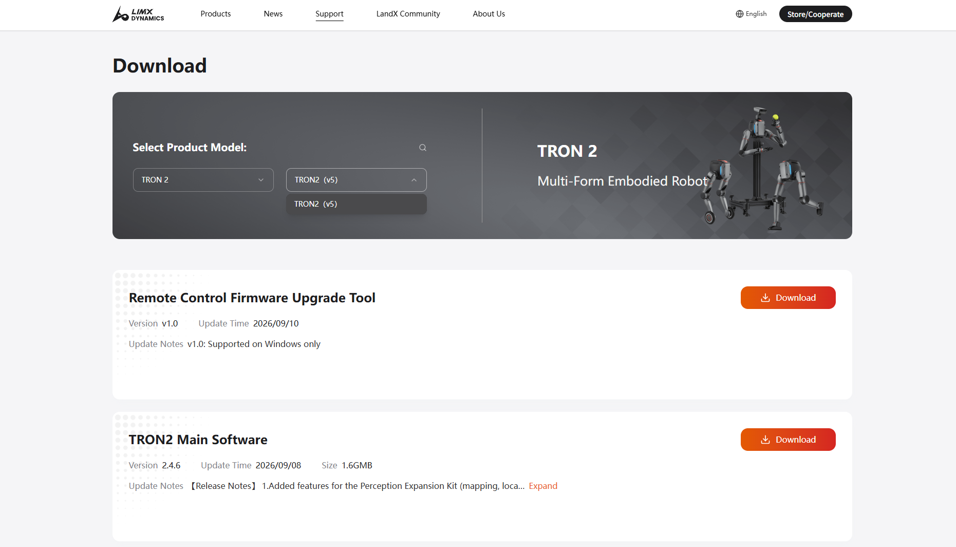
b. On the robot management page, go to the Version Management section. Select the firmware type you wish to upgrade, click Select file to upload the firmware package, then click the Upgrade button after the upload is complete. Wait patiently for the upgrade to finish.
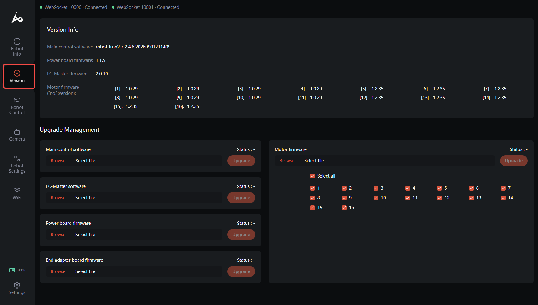
c. Note: Upgrading the motor driver firmware must be done in two steps (this applies to both the dual-arm configuration and the bipedal/wheeled-leg configuration). First, select all motors, choose the downloaded "TRON2 – Motor Driver Firmware", and click Upgrade.
Then, select all motors again, choose the downloaded "TRON2 – Motor Driver Firmware Supplementary Package", and click Upgrade.
d. Note: The robot will automatically restart after certain firmware upgrades are completed.
7.2 Upgrading the VR Device App Online
Before proceeding, make sure the VR device is connected to an external network.
- Open the Library from the bottom menu of the VR device and find the teleoperation app. Press and hold the Grip Button on the controller, then select "Uninstall" in the pop-up window.
- Open the browser on the VR device, search for "LimX Dynamics", and go to the LimX Dynamics official website.
- Go to "Support > Downloads", select
TRON 2, and download the latest VR device app. - When the download is complete, select "Install app" in the pop-up installation prompt and wait for the installation to finish.
- After installation, you can find the teleoperation app in the Library.
Operation Video
7.3 The remote controller firmware upgrade
The remote controller firmware upgrade tool runs on Windows only.
- Download the remote controller firmware upgrade tool from the official website, unzip it, and open the software.
- Take out the remote controller charging cable and connect the remote controller to be upgraded to a Windows PC.
- With the remote controller powered off, press and hold the Left Joystick + Power button. The remote controller will enter Boot state.
- In the "COM" field, select the device number of the remote controller, then click "OPEN COM" to open the remote controller serial port.
- After the serial port is opened, the remote controller log information will be displayed, and the status shown on the remote controller screen will switch to "BootUSB".
- Download the latest remote controller firmware from the official website and save it locally. Click "OPEN FILE" and select the downloaded new firmware.
- Click "UPGRADING" to start the firmware upgrade. A prompt will pop up after the upgrade is successful.
Operation Video
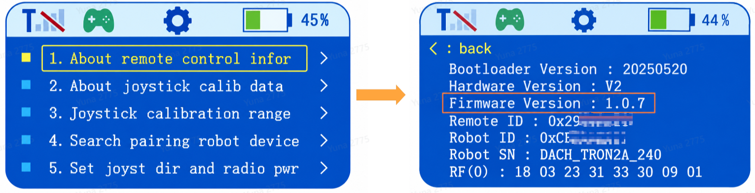
Long press the power button to turn off the remote controller. After restarting, you can verify the upgraded firmware version: double-click the Power button to enter the settings page, use the Up/Down buttons to select the first item, then press the Right button to enter. The remote controller information will be displayed, where "Firmware Version" is the current firmware version.
8 Log Export
- Connect to the robot Wi-Fi. Password:
12345678. - Enter the following in the browser address bar:http://10.192.1.2:8090 to enter the log management interface.
- Export the log files and bag files from the time when the issue occurred.
9 Routine Care and Maintenance
9.1 Cleaning and Storage
- Clean the surface regularly or after operation in dusty environments using a clean microfiber cloth.
- Use the transport case designed specifically for the TRON 2 robot for storage and transport to prevent impact and vibration.
9.2 Inspection and Maintenance
- Exterior maintenance: Clean dust from joint areas and check whether screws are loose.
- Software updates: Upgrade official firmware in a timely manner to fix potential system vulnerabilities and optimize motion algorithms.
- Battery pack: Charge to 50%-60% before storage (avoid full charge or deep discharge), and recharge to the same range every 3 months.
- Remote controller: Keep interfaces clean, ensure the joysticks are not subjected to external force during storage, and regularly check anti-interference performance.